If we take a look at the code we can see that we have the sensor pins defined on pin 8 and 9. Using interruptions we detect when the first sensor is triggered and we save the time value. Then we detect the second sensor and we equal the time to the difference between the actual time and the previous time. This will be in microseconds so we divide it by 1 million so we get seconds. Then we divide the distance between the sensors by that time value. By the way you should manually measure the distance between the sensors with a rouler. Then get in the code and change that value according to your distance. We get the speed and we divide it in digits and print those to the seven segment display. That’s it for the code.
//Pins of the 7 segment display
#define MAX7219_Data_IN 2
#define MAX7219_Chip_Select 3
#define MAX7219_Clock 4
//Inputs/Outputs
int but_1 = 10; //Left button
int but_2 = 11; //Right button
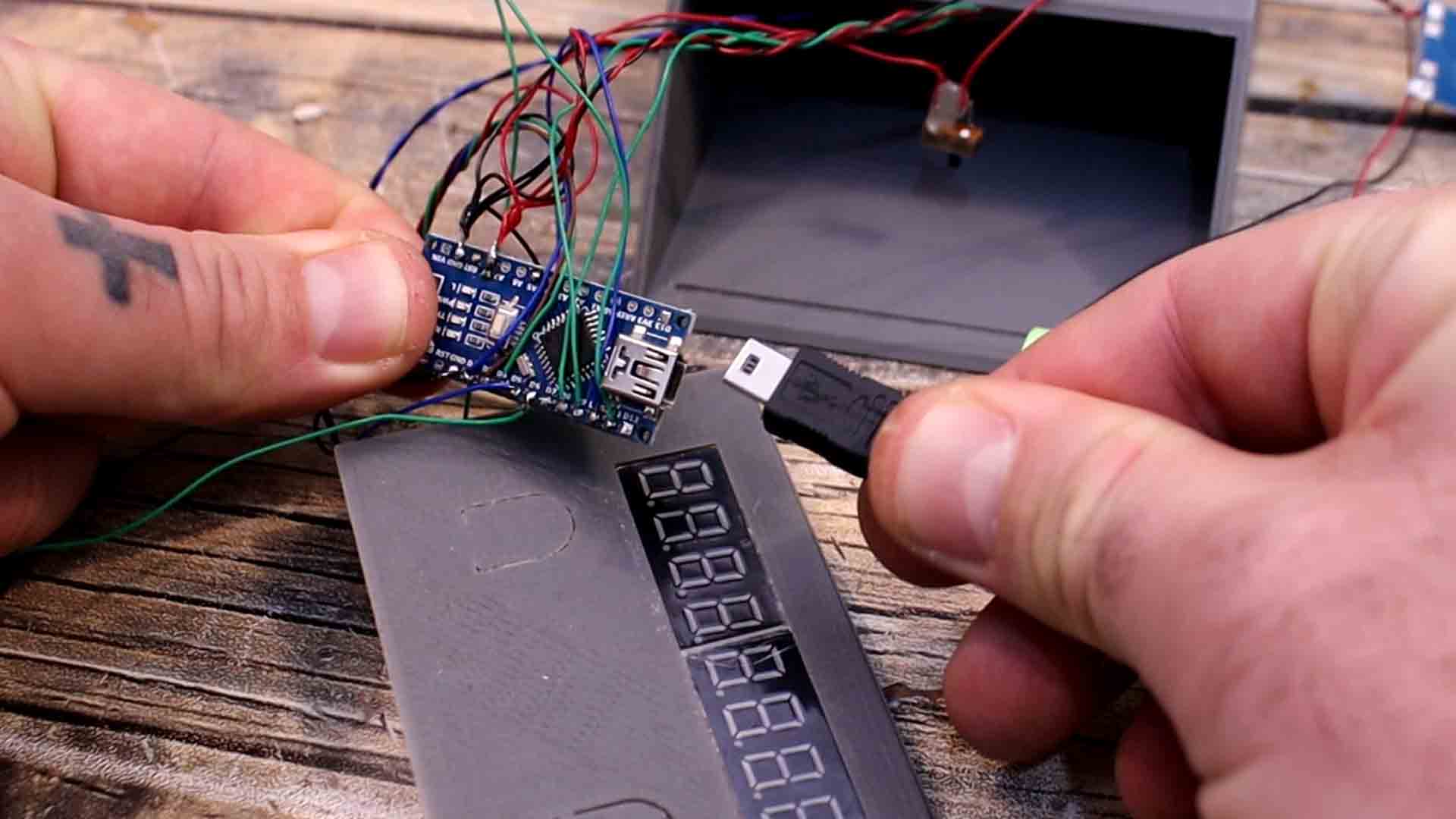
int sensor_1 = 8; //Front sensor
int sensor_2 = 9; //Rear sensor
int Buzzer = 6; //Buzzer
//Variables
float distance_between = 0.18; //Add your distance in "meter" units
//Variables used in the code...
unsigned long counter_1, current_time, time_interval;
byte last_CH1_state, last_CH2_state;
float Speed, last_speed;
bool but_2_state = false;
//Function to send bytes to the 7 seg display
void shift(byte send_to_address, byte send_this_data)
{
digitalWrite(MAX7219_Chip_Select, LOW);
shiftOut(MAX7219_Data_IN, MAX7219_Clock, MSBFIRST, send_to_address);
shiftOut(MAX7219_Data_IN, MAX7219_Clock, MSBFIRST, send_this_data);
digitalWrite(MAX7219_Chip_Select, HIGH);
}
void setup() {
pinMode(sensor_1, INPUT);
pinMode(sensor_2, INPUT);
pinMode(but_1, INPUT_PULLUP);
pinMode(but_2, INPUT_PULLUP);
pinMode(Buzzer, OUTPUT);
digitalWrite(Buzzer,LOW);
PCICR |= (1 << PCIE0); //enable PCMSK0 scan
PCMSK0 |= (1 << PCINT0); //Set pin D8 trigger an interrupt on state change.
PCMSK0 |= (1 << PCINT1); //Set pin D9 trigger an interrupt on state change.
pinMode(MAX7219_Data_IN, OUTPUT);
pinMode(MAX7219_Chip_Select, OUTPUT);
pinMode(MAX7219_Clock, OUTPUT);
digitalWrite(MAX7219_Clock, HIGH);
delay(200);
//Setup of MAX7219 chip
shift(0x0f, 0x00); //display test register - test mode off
shift(0x0c, 0x01); //shutdown register - normal operation
shift(0x0b, 0x07); //scan limit register - display digits 0 thru 7
shift(0x0a, 0x0f); //intensity register - max brightness
shift(0x09, 0xff); //decode mode register - CodeB decode all digits
shift(0x08, 0x00); //digit 7 (leftmost digit) data
shift(0x07, 0x00);
shift(0x06, 0x00);
shift(0x05, 0x00);
shift(0x04, 0x00);
shift(0x03, 0x00);
shift(0x02, 0x00);
shift(0x01, 0x00);
Serial.begin(9600);
}
void loop() {
Speed = distance_between/(time_interval/1E6);
if(Speed != last_speed){
byte digit_1 = Speed/100;
byte digit_2 = (Speed - (digit_1*100))/10;
byte digit_3 = Speed - (digit_1*100) - (digit_2*10);
shift(0x03, digit_1);
shift(0x02, digit_2);
shift(0x01, digit_3);
tone(Buzzer, 1000, 300);
}
last_speed = Speed;
if(!digitalRead(but_2) && but_2_state){
but_2_state = false;
reset_screen();
tone(Buzzer, 1500, 1000);
}
else if(digitalRead(but_2) && !but_2_state){
but_2_state = true;
}
Serial.println(Speed);
//delay(200);
}
ISR(PCINT0_vect){
//First we take the current count value in micro seconds using the micros() function
current_time = micros();
if(PINB & B00000001){ //We make an AND with the pin state register, We verify if pin 8 is HIGH???
if(last_CH1_state == 0){ //If the last state was 0, then we have a state change...
last_CH1_state = 1; //Store the current state into the last state for the next loop
counter_1 = current_time; //Set counter_1 to current value.
}
}
else if(last_CH1_state == 1){ //If pin 8 is LOW and the last state was HIGH then we have a state change
last_CH1_state = 0; //Store the current state into the last state for the next loop
}
if(PINB & B00000010 ){ //pin D9 -- B00000010
if(last_CH2_state == 0){
last_CH2_state = 1;
time_interval = current_time - counter_1;
}
}
else if(last_CH2_state == 1){
last_CH2_state = 0;
}
}
void reset_screen() {
shift(0x07, 0x00);
shift(0x06, 0x00);
shift(0x05, 0x00);
shift(0x04, 0x00);
shift(0x03, 0x00);
shift(0x02, 0x00);
shift(0x01, 0x00);
}
void print_int(int pos, int data){
if(pos==1){
shift(0x01, 0x00);
}
}