Panel Cookies
Balancing Robot - Schematic
02/10/2021 | Views: 16965 | Arduino | by: ELECTRONOOBS      


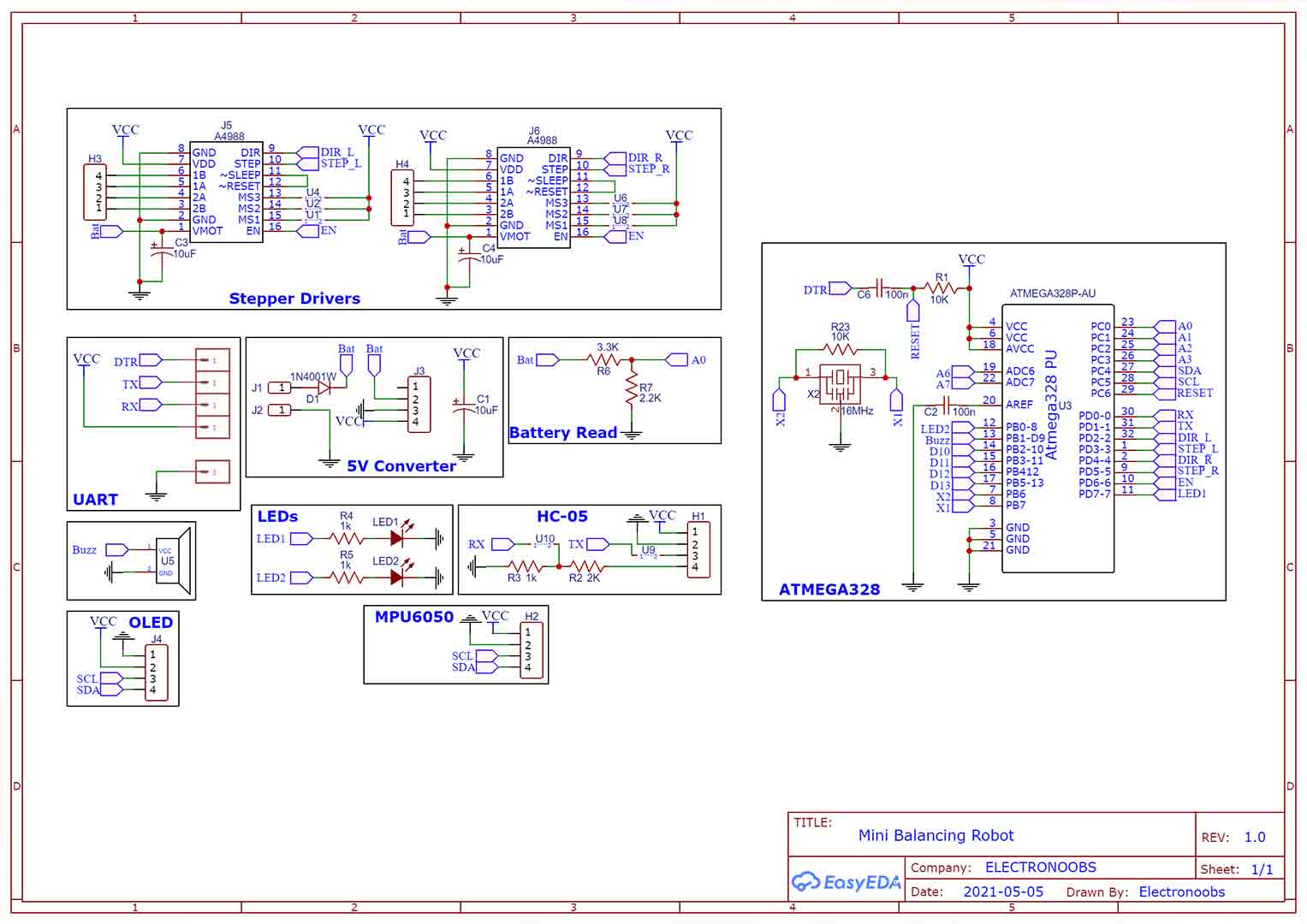
The schematic for the PCB is below. The battery, the main ON and Off switch and the motors are connected externally. Make sure you connect the NEMA 17 motor with conenctiosn in this order: 1B 2A 1A 2B. The rest of the connections are made on the PCB. The Buck converter is also external so make sure you connect in the right way. Make sure is fiexd at 5V.


Last tutorials

All about Arduino PWM frequencies
Debug Arduino and ESP with PlatformIO
Homemade Best Two Hand Multimeter with Arduino
Homemade Baby White Noise Generator
Measure AC RMS with Arduino

ADVERTISERS


>

Affiliate Disclosure

ADVERTISERS


PCBWAY PCB service


Curso Arduino Online nivel Intermedio