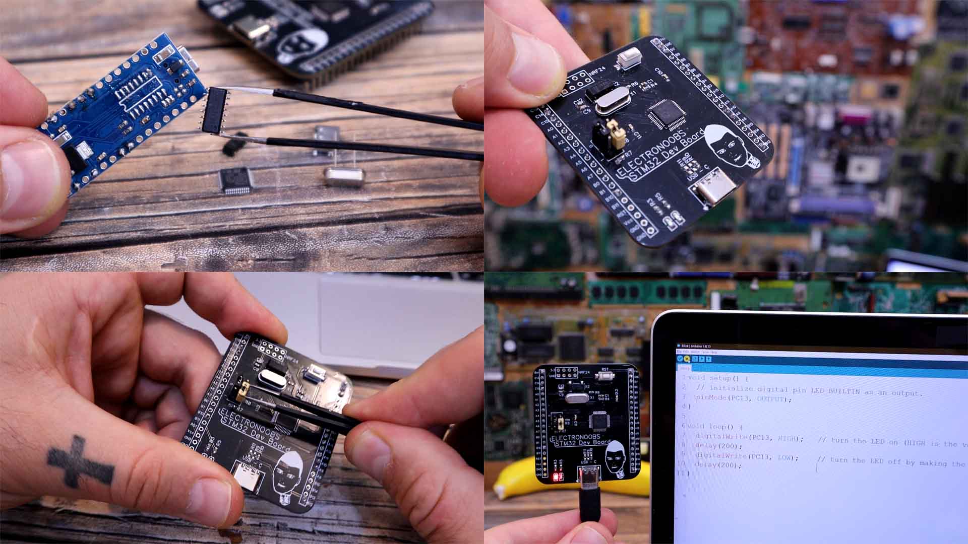
Let me show you my PCB that I’ve made based on this same microcontroller. It has the same pinout all around as the "blue pill" since this PCB is just for tests. It also has the SPI pins for the NRF24 radio module so I can test the connection for a future project of mine.
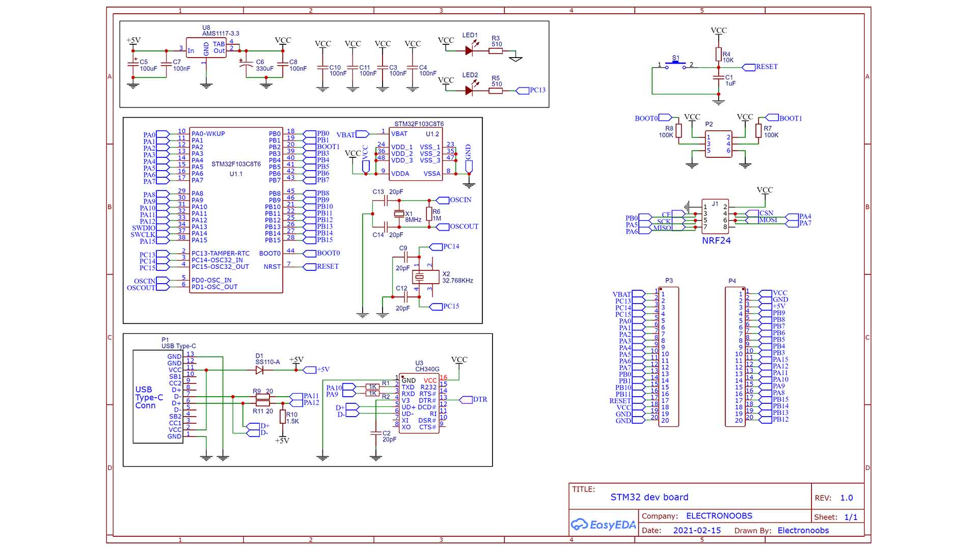
Ok, below you will find the basic configuration of this microcontroller. So in order for it to work, at least we need these components. It needs a pullup on the reset pin and we need the 8MHz crystal and 32KHz resonator each with two 20pF capacitors connected. To get 3.3V I’ve used the AMS1117 regulator and supplied the output to the VDD pins. For the boot1 and boot 2 connections I’ve placed 6 pins so I could also use jumpers to make the switch.
Apart from the basic configuration I’ve also added the CH340 UART programmer. This is connected to the D+ and D- pins from the USB type C connector and from this programmer is connected to the RX and TX pins of the UART por. That’s how this board could be programmed with the USB connector
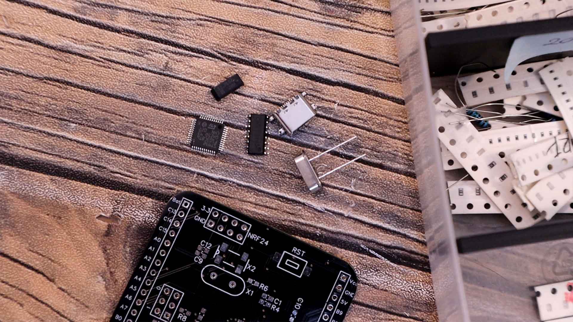
I gather all the needed components such as resistors, capacitors, crystal oscillators, the regulator, the microcontroller and so on. I have the CH340 programmer from an old Arduino NANO that doesn’t work anymore. I solder everything on the PCB. I connect the USB cable. The COM appears on my Arduino IDE.
Using the serial method, I upload another code that will make the LED blink each 200 ms. Remember to place the jumper in the 1 position. Upload the code and there you go, the PCB works with no problems so I could use this setup for my future PCBs. Nice right?
void setup() {
  // initialize digital pin LED_BUILTIN as an output.
  pinMode(PC13, OUTPUT);
}

// the loop function runs over and over again forever
void loop() {
  digitalWrite(PC13, HIGH);           // turn the LED on (HIGH is the voltage level)
  delay(200);                        // wait for a second
  digitalWrite(PC13, LOW);            // turn the LED off by making the voltage LOW
  delay(200);                        // wait for a second
}That's how to program the STM32 on your own PCB design. I hope you like this tutorial and maybe you have learned something new. If my videos help you, consider supporting my work on my PATREON or a donation on my PayPal. Thanks again and see you later guys.