
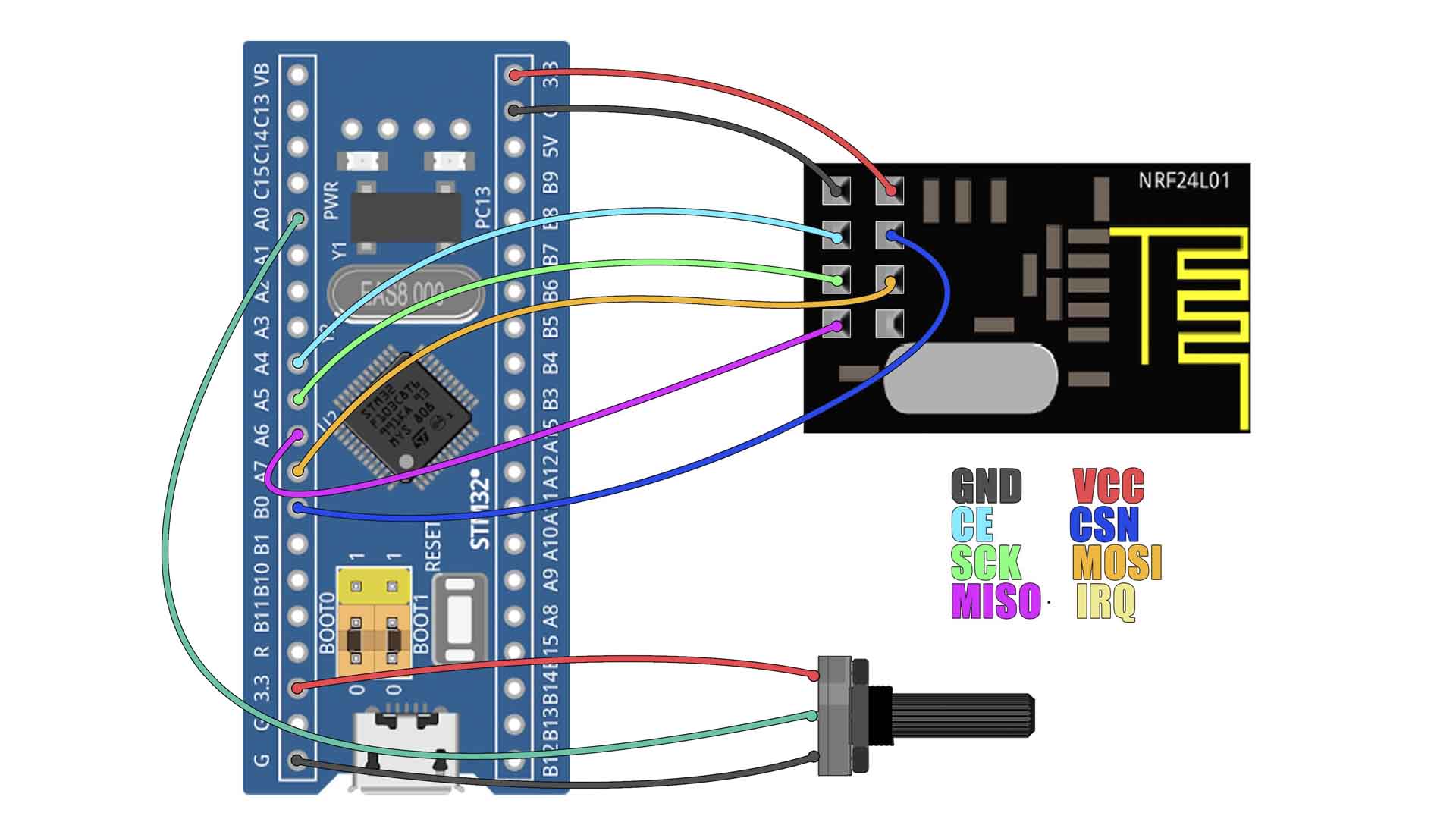
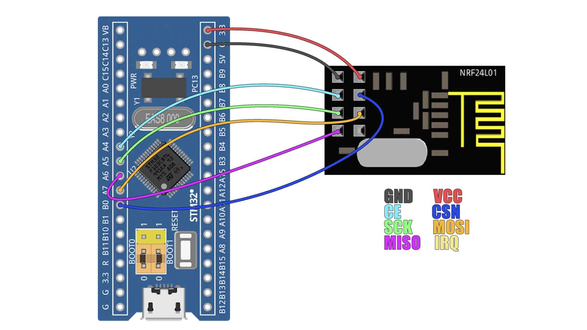
I wanted to test these STM32 microcontrollers with the NRF24 radio library. Now remember that the NRF24 uses SPI communication. If we take a look at the board pinout, we can see we have the default SPI port on pins A7 for MOSI, A6 for MISO and A5 for clock. The CS and CSN pins could be any digital pin and can be declared in the code and in my case, I will connect them to PB0 and PA4.
The STM32F103C is a 32 bits architecture microcontroller. Compared with the Arduino UNO NANO or the MEGA for example, which are 8 bits microcontrollers, this chip has 32 bits so it could move 4 times more bits on a single clock pulse so just with that it would be at least 4 times faster. On top of that, this could run by default at 72Mhz and if you remember the Arduinos UNO, NANO or the MEGA are running at just 16MHz, so that is once again 4.5 times faster. You could also overclock the STM32 up to 128MHz which is crazy. This is the pinout of this microcontroller and it has 26 I/O pins with interruptions for all, it has 10 analog inputs and the ADC is of 12bits so it has 4 times more resolution than the ATmega328 for example which has 10 bits ADCs. Internally it has 7 timers, two I2C ports, 3 UART ports, 2 SPI ports, and the PWM pins are of 16 bits, so 65 thousand values, so yeah, this microcontroller is awesome.
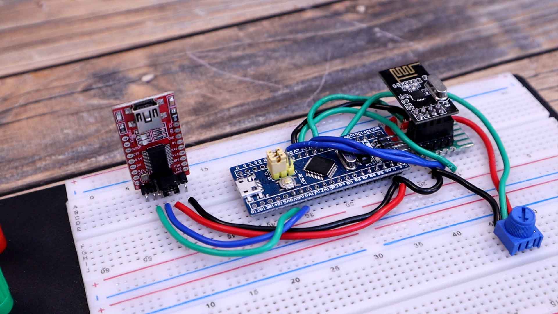
So, make these connections between the STM32 and the NRF24 module. Then download the code and open it in Arduino. We change the CS and CSN pins from 9 and 10 in case of the Arduino to PB0 and PA4 for the STM32. The rest of the code is the same. I read the potentiometer value from the analog input pin PA0 and send that value with the NRF24 connection. I upload the code for the transmitter to the STM32 and I'll send the value from this potentiometer.
#include <SPI.h>
#include <nRF24L01.h>       //Download here: https://electronoobs.com/eng_arduino_NRF24_lib.php
#include <RF24.h>

RF24 radio(PB0, PA4);
const uint64_t address = 0xE8E8F0F0E1LL;
int pot1 = PA0;

struct MyData {
  byte throttle;
};
MyData data;

void setup() {
  Serial.begin(9600);
  pinMode(pot1, INPUT);
  radio.begin();
  radio.setAutoAck(false);
  radio.setDataRate(RF24_250KBPS);
  radio.openWritingPipe(address);
}

void loop()
{
  data.throttle = map(analogRead(pot1),0, 4096,0,255);
  radio.write(&data, sizeof(MyData));
  digitalWrite(LED,state);
  state = !state;
  delay(1);
}
To receive the data, in my case, I'm using my NRF24 tester made with Arduino, but you could also use the STM32 and print the values on the serial monitor. My tester will print the received value on the OLED screen and also change the brightness of the LED. As you can see, I can receive the value from the potentiometer so the transmitter with the STM32 works good and I think I can get even more speed.
/* Receiver code for the STM32 + NRF24
 * Install the NRF24 library to your IDE
 * Upload this code to the STM32F103C series
 * Connect a NRF24 module to it:
 *
    Module // STM32

    GND    ->   GND
    Vcc    ->   3.3V
    CE     ->   PA4
    CSN    ->   PB0
    CLK    ->   PA5
    MOSI   ->   PA7
    MISO   ->   PA6

This code receive 1 channels and prints the value on the serial monitor
Please, like share and subscribe : https://www.youtube.com/c/ELECTRONOOBS
*/

#include <SPI.h>
#include <nRF24L01.h>       //Download here: https://electronoobs.com/eng_arduino_NRF24_lib.php
#include <RF24.h>

//Remember that this code is the same as in the transmitter
const uint64_t pipeIn = 0xE8E8F0F0E1LL;
RF24 radio(PB0, PA4); // PB0 - CE, PA4 - CSN on Blue Pill

// The sizeof this struct should not exceed 32 bytes
struct Received_data {
  byte throttle;
};

int ch1_value = 0;
Received_data received_data;
int LED = 5;

/**************************************************/

void setup()
{
  Serial.begin(9600);
  //We reset the received values
  received_data.throttle = 127;
  pinMode(LED, OUTPUT);
  analogWrite(LED, LOW);
  //Once again, begin and radio configuration
  radio.begin();
  radio.setAutoAck(false);
  radio.setDataRate(RF24_250KBPS);
  radio.openReadingPipe(1,pipeIn);

  //We start the radio comunication
  radio.startListening();
}

/**************************************************/

unsigned long last_Time = 0;

//We create the function that will read the data each certain time
void receive_the_data()
{
  while ( radio.available() ) {
  radio.read(&received_data, sizeof(Received_data));
  last_Time = millis(); //Here we receive the data
}
}

/**************************************************/

void loop()
{
  //Receive the radio data
  receive_the_data();
  int val = received_data.throttle;
  analogWrite(LED, val);
  Serial.println(val);
}//Loop end
Run the codes and you will see the value from the potentiometer printed on the receiver serial monitor. IUn my case I've used the OLED display so we can better see the recived data on the video, but the serial monitor should work the same.
That's how to program the STM32 to wirk with NRF24 using the Arduino IDE platform. I hope you like this tutorial and maybe you have learned something new. If my videos help you, consider supporting my work on my PATREON or a donation on my PayPal. Thanks again and see you later guys.


