See how I've made my own PCB for the well know circuit of ATtiny85 Arcade game. Here you will have the schematic, part list, step by step of soldering components, how to burn bootloader and how to upload codes for different games to the ATtiny85. I know this is nothing new and you have more here on the original GitHub post. But I hope you will learn something new.
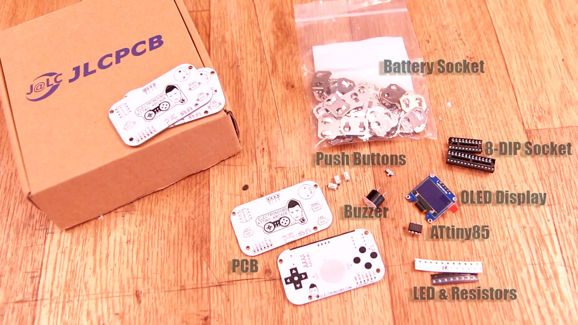
The part list is short. Get the PCB GERBERs and order the PCB from any manufacturer. THis will be quite cheap. Once you have the PCB get all the parts below. You can solder the ATtiny85 directly on the PCB but is better to use the 8-DIP socket so we could remove the chip anytime. The LED could be of any color that you want. The rest are basic components. Remember to order a CR2032 battery as well.
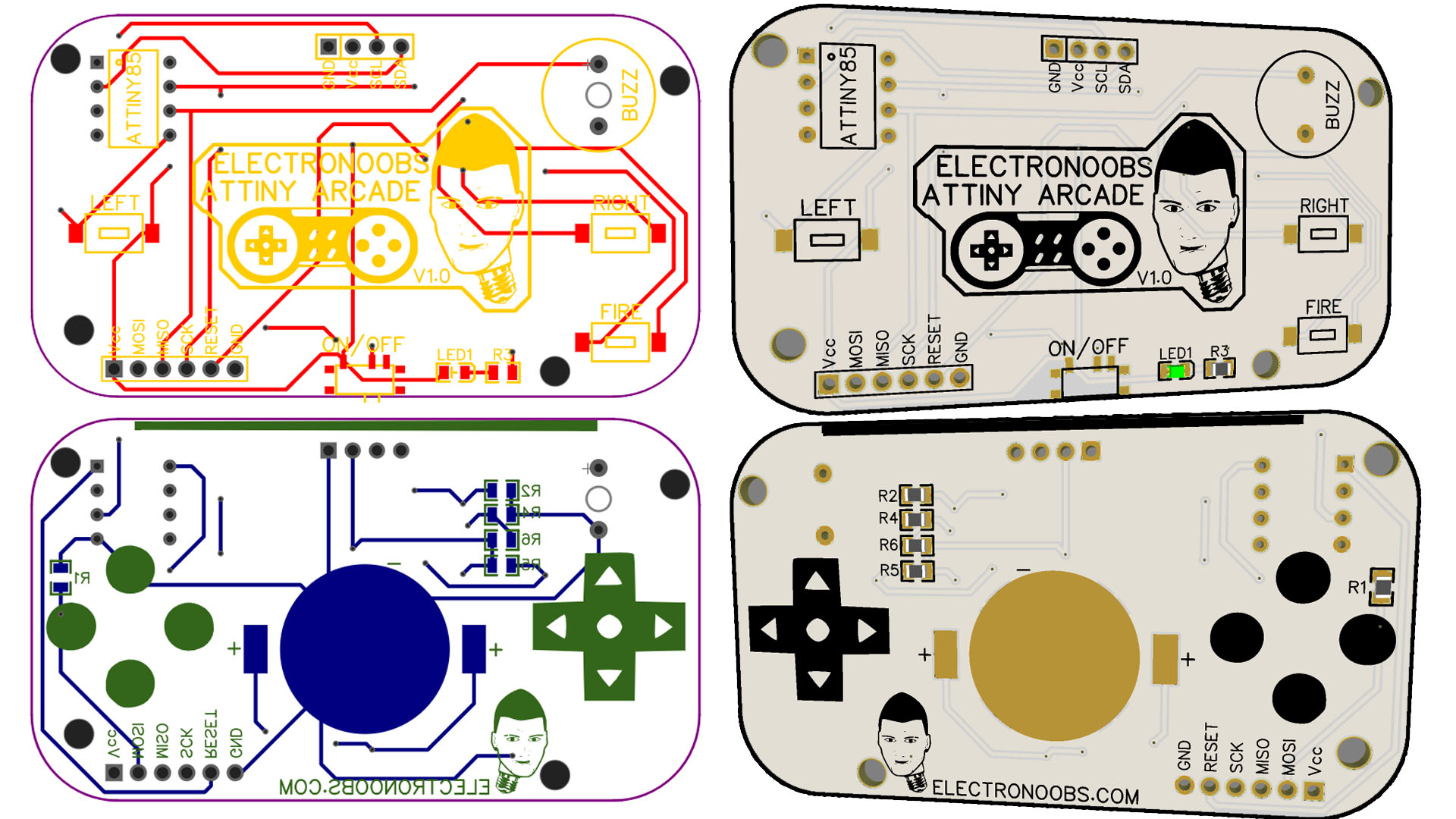
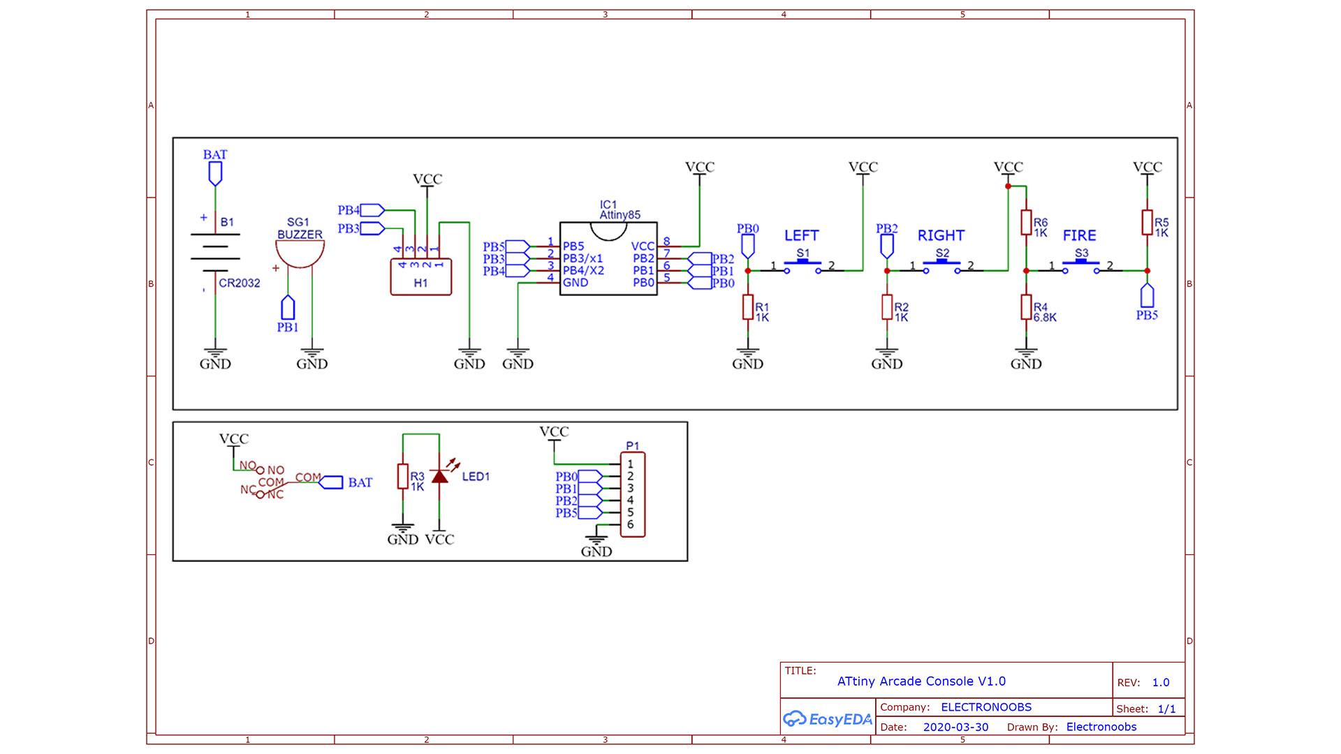
The connections are very easy. The ATtiny has 6 pins taht we could use and a supply of 3V from the battery and GND pin. Don't worry, the chip works fine at 3V and the same for the rest of the components. The buttons have a pulldown and are conencted to pins PB0, 2 and 5. The OLED display needs i2c communication and that is created on pins PB4 and PB3 for data and clock. We have the SPI port for ISP programming with the Arduino.
Go to the link below and get the GERBER files for the PCB. Then send those files to any PCB manufacturer and get the boards. In my case, the solder mask coler is white with black color silklayer. The board is 70 by 40mm so is not taht big. If you want, use the schematic above and make your own PCB. When you have the PCB, we can start soldering components.
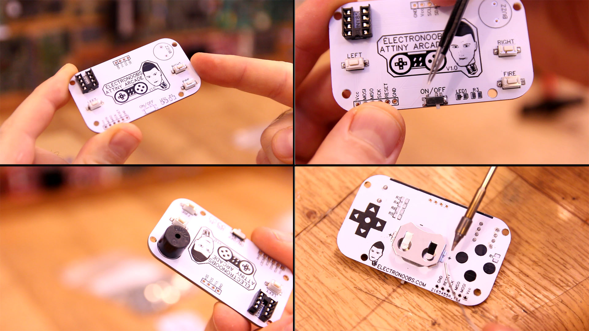
First step is to solder the 8-DIP solder on the top layer of the PCB. Then solder those 3 SM push buttons. Next, solder the sliding switch. We add the buzzer facing the top side PCB so the sound will get twoards us. Then, flip the PCB adn you can solder the battery socket.
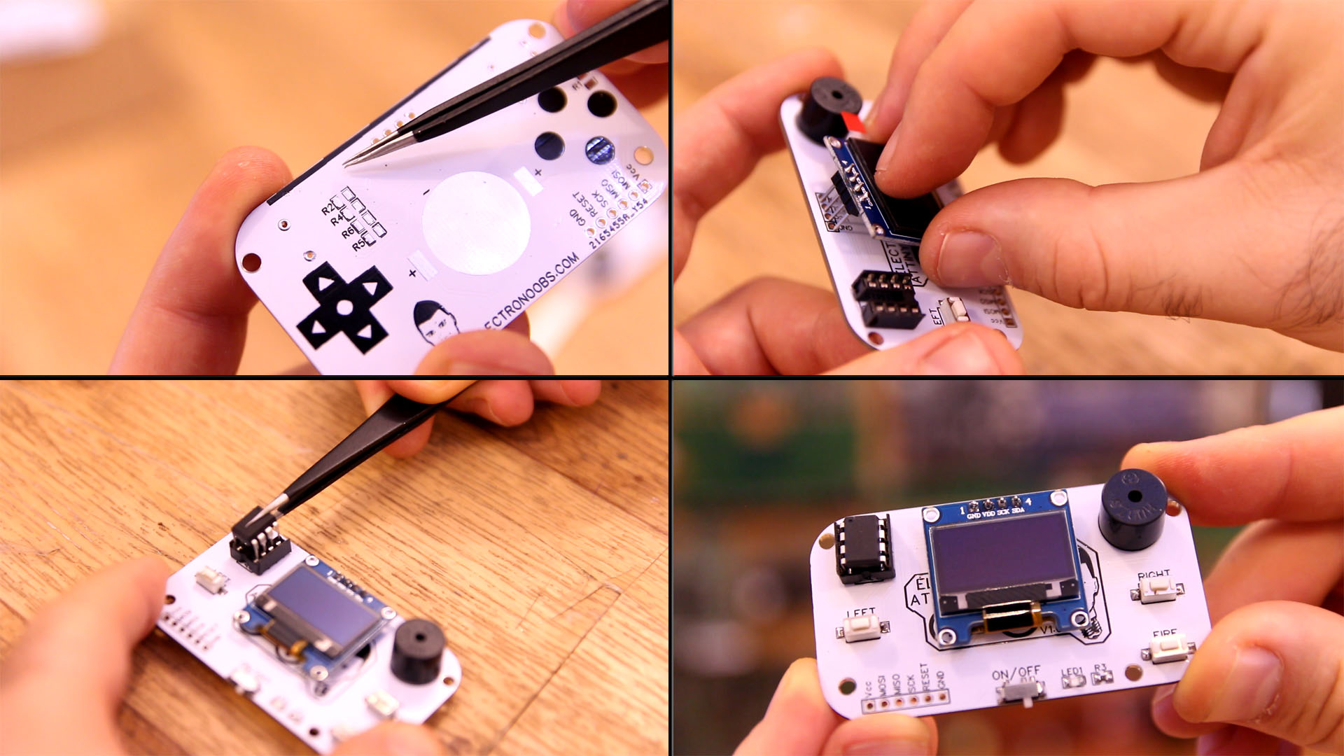
Remember to solder all the resistors with the valeus from the Schematic. When these components are soldered, we can solder the OLED display. Final step is to add the ATtiny85 microcontroller. Make sure which is the first pin and don't place it backwards. We can now program the chip.
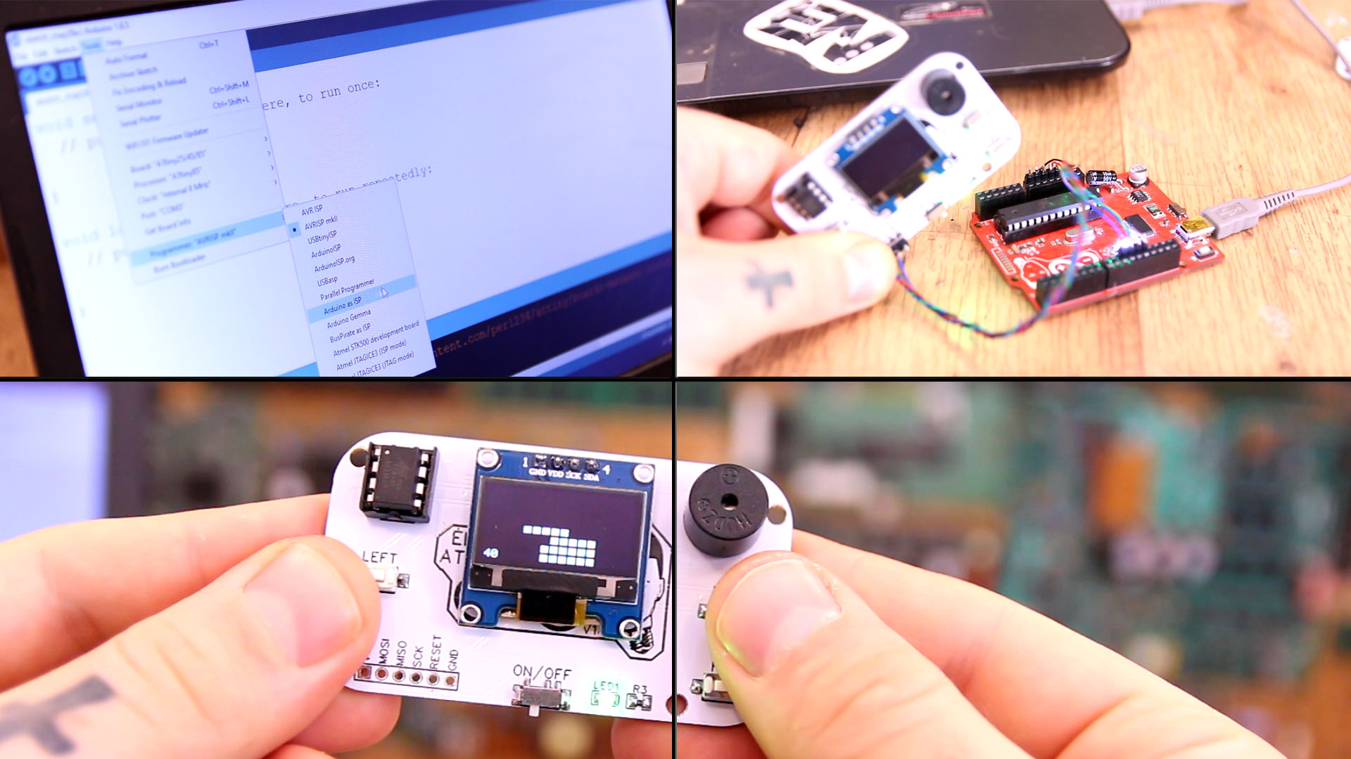
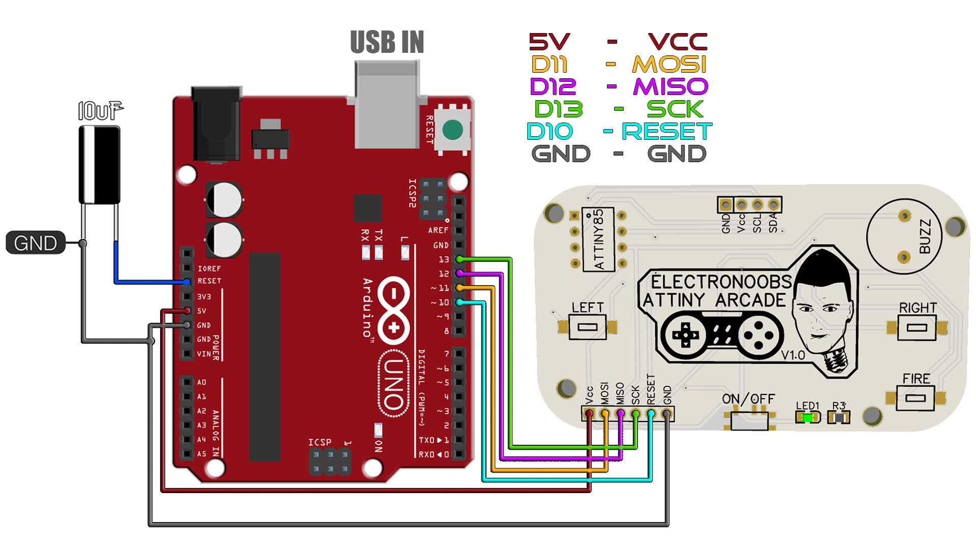
Ok, we have to burn a bootloader to the chi adn then uplaod the code. For both those steps we need the connections below to an Arduino. In my case I will use Arduino UNO. So, make the connections as below between the Arduino SPI port and the PCB. We will sue the Arduino as ISP to uplaod codes.
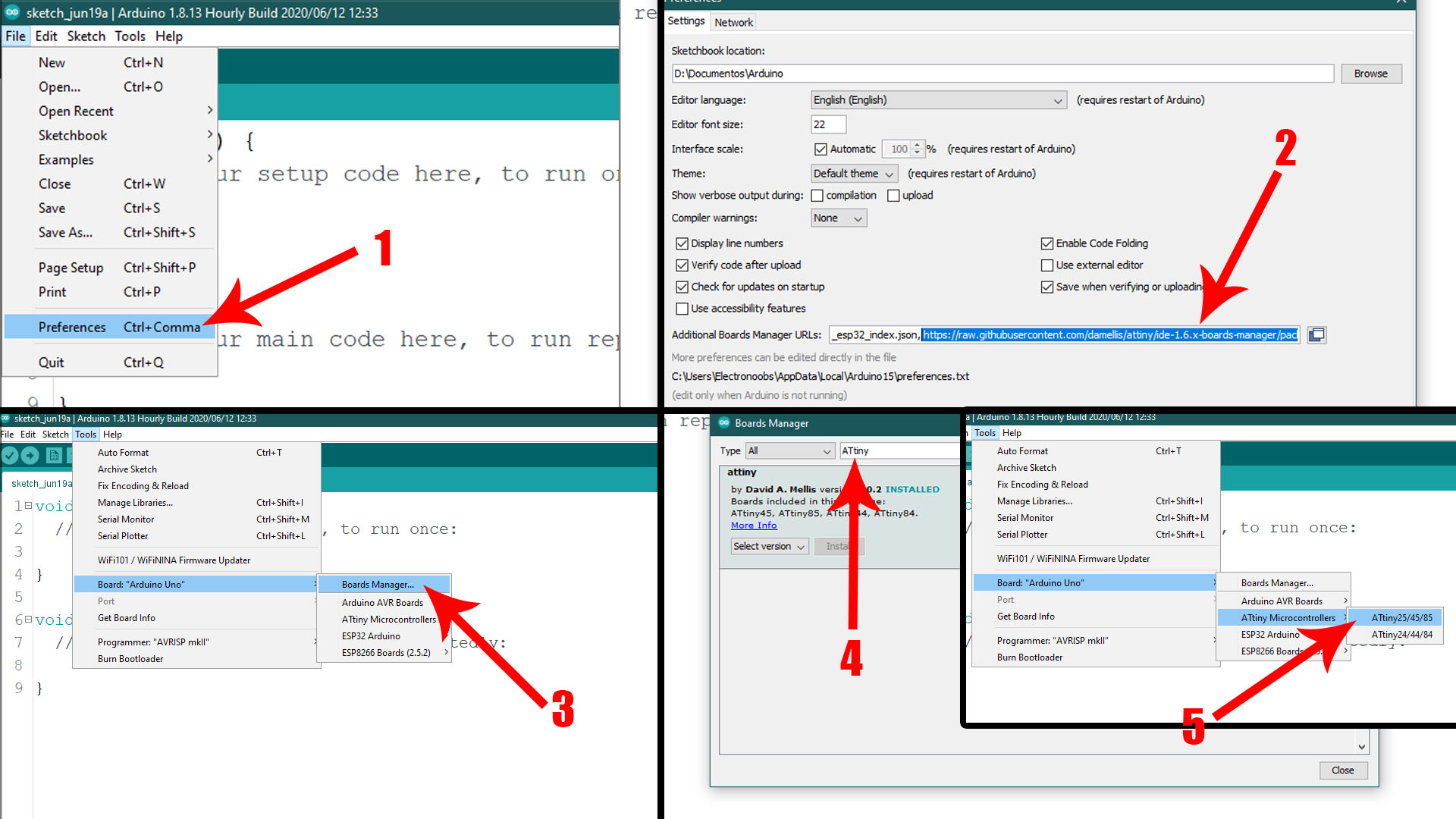
Run your Arduino IDE. We need to install the ATtiny85 boards in case that you don't already have that. To install the boards, copy the link below. Go to Ardduino IDE, to File -> Preferences -> Paste the link in the "Additional Boards Manager URLs". If you already have another link ther, add a comm "," first and then paste the new link. Save and close preferences. Now go to Tools -> Board -> Boards Manager. In this manager search for ATtiny adn install the attiny boards. Now, if you go on tool -> board, you should see the ATtiny boards as well.
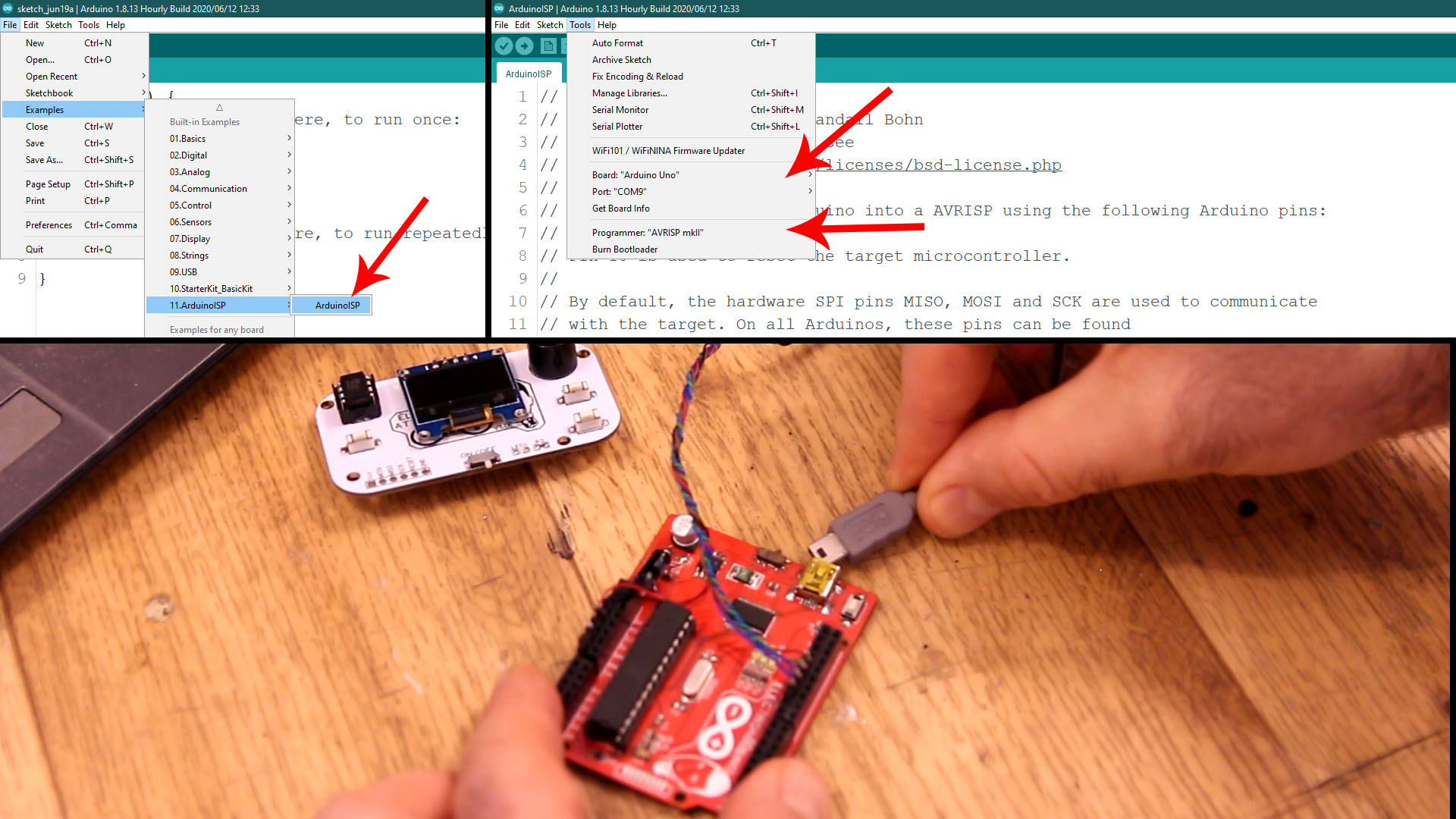
In order to use the Arduino as an ISP programmer, we need to uplaod a code to it so for taht, go to Examples -> ArduinoISP -> ArduinoISP and open that example code. Then make sure yous elect the type of board for your Arduino, in my case, Arduino UNO. Select the com and leave the default programmer as "AVRISP mkII". Connect the USB, select the COM and uplaod the code to the Arduino UNO.
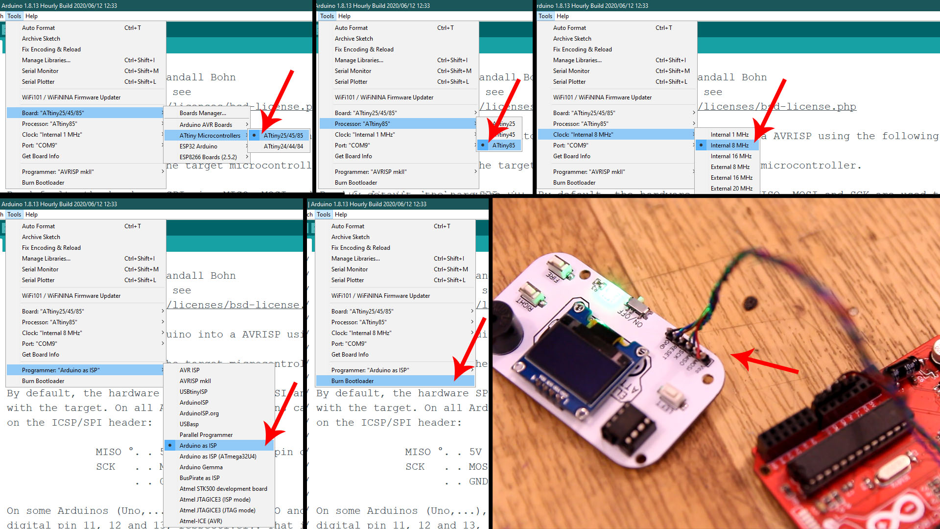
Ok, now the Arduino has the ISP code so it will act as a ISP programmer. Now, let's butn the bootloader. Go to Tools -> Board and selectt the ATtiny25/45/85 type of board. Then, once that is selected, go to Tools -> Processor -> And select the ATtiny85. Then go to Clock -> and select the internal 8MHz one so we will burn that bootlaoder. Go to Tools -> Programmer and make sure you now change the normal programmer from "AVRISP mkII" to "Arduino as ISP". Finally, amke sure the Arduino UNO is connected to the PCB to the ISP port and go to Tools -> Burn Bootloader. The Arduino Rx/Tx LEDs will blink and after a while you will get the bootloader burn complete on the screen.
Go to the link below adn download a .ZIP file with all the games compatible with this PCB, or go to the original GitHub post and see all the games. Then, open any game in Arduino IDE. Make sure that the "Arduino as ISP" programmer is still selected and the ATtiny85 board with 8MHz clock. Connect the Arduino UNO to the PCB at the ISP port, compile the code and click upload. The game will now upload to the ATtiny85. That's it! Play!
I hope that you like this tutorial. If you consider supporting my work, buy my PCB on my shop, or maybe consider supporting me on PATREON or if you want, make a PayPal donation. Thank you very much.