
If you want a better radio controller using the same configuration, see this previous tutorial. That controller si compatible with this done. For the radio controller follow the same steps as for the drone PCB. See the schematic of the PCB below and use the same values. This time we supply the PCB with 9V battery so we have 2 voltage regulators, one for 5V and another for 3.3V. We will sue a power amplified antenna NRF24 module for more range.
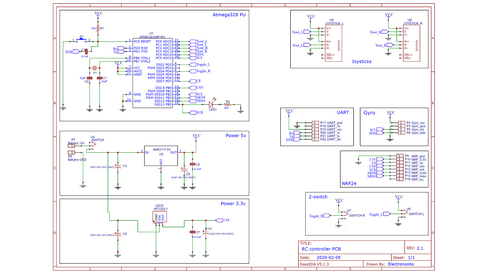
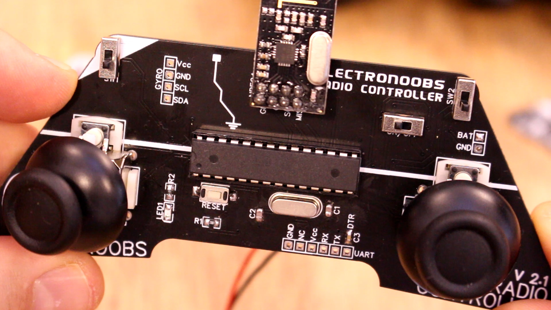
For the radio controller follow the same steps as for the drone PCB. Check the part list here and solder the components in this order: First, the ATmega328p-PU chip, with the R1 resistor of 10K, the C3 capacitor of 100nF, the crystal of 16MHz and the C2 and C1 of 22pF. You can also solder the LED1 and R2 of 330R and the push button for reset. Then test if you can upload a sketck. If you need a bootloader, use the SPI pads below and burn it as in the previous part.
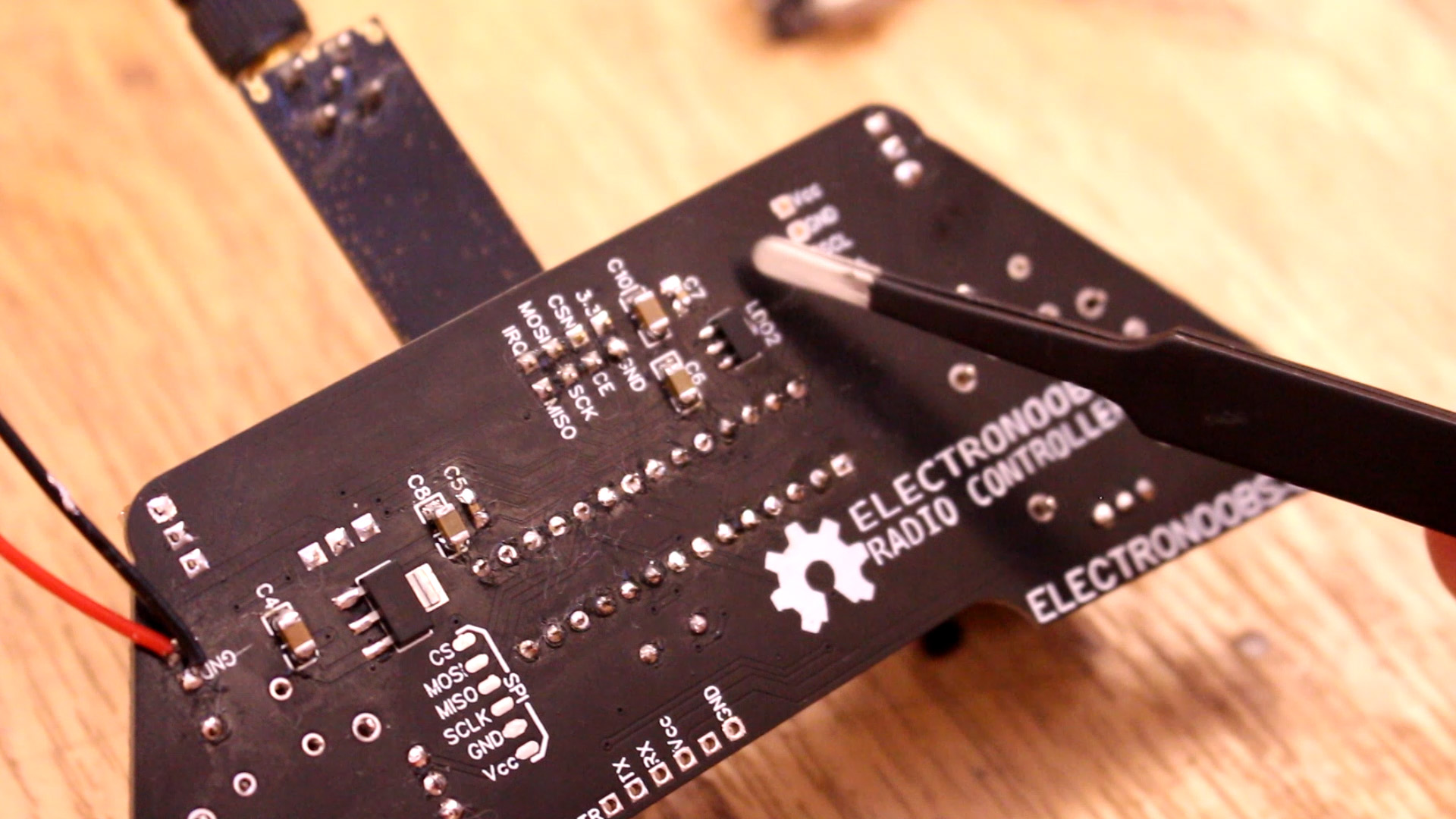
If the ATmega328 chip works, solder the rest. First solder the voltage regulators. After you solder the LDOs and capacitors, connect 9V at the input and check for 5V and 3.3V with your multimeter. Make sure you have good values. If everything is ok, solder all the rest of the components.
Go below and download the radio controller code. Open it in Arduino IDE. Select Arduino UNO board and uplaod it to the PCB using the FTDI programmer once again. Now you can test if you can receive values to the MultiWii platform with the drone conencted as you can see below. you might need to tune a little bit the joystick values in order to be exactly in the middle. If not, use my previous radio controller with digital adjustment from this tutorial.
Ok, now add the propellers and the battery. Make sure you calibrate the accelerator in the multiwii paltform. Make sure the propellers will rotate in the directions as below and that they will push the air downwards. Flip the swith of the drone and radio controller. Flip the AUX 2 swith in order to enable the motors. Then increase throttle and the drone will go up.
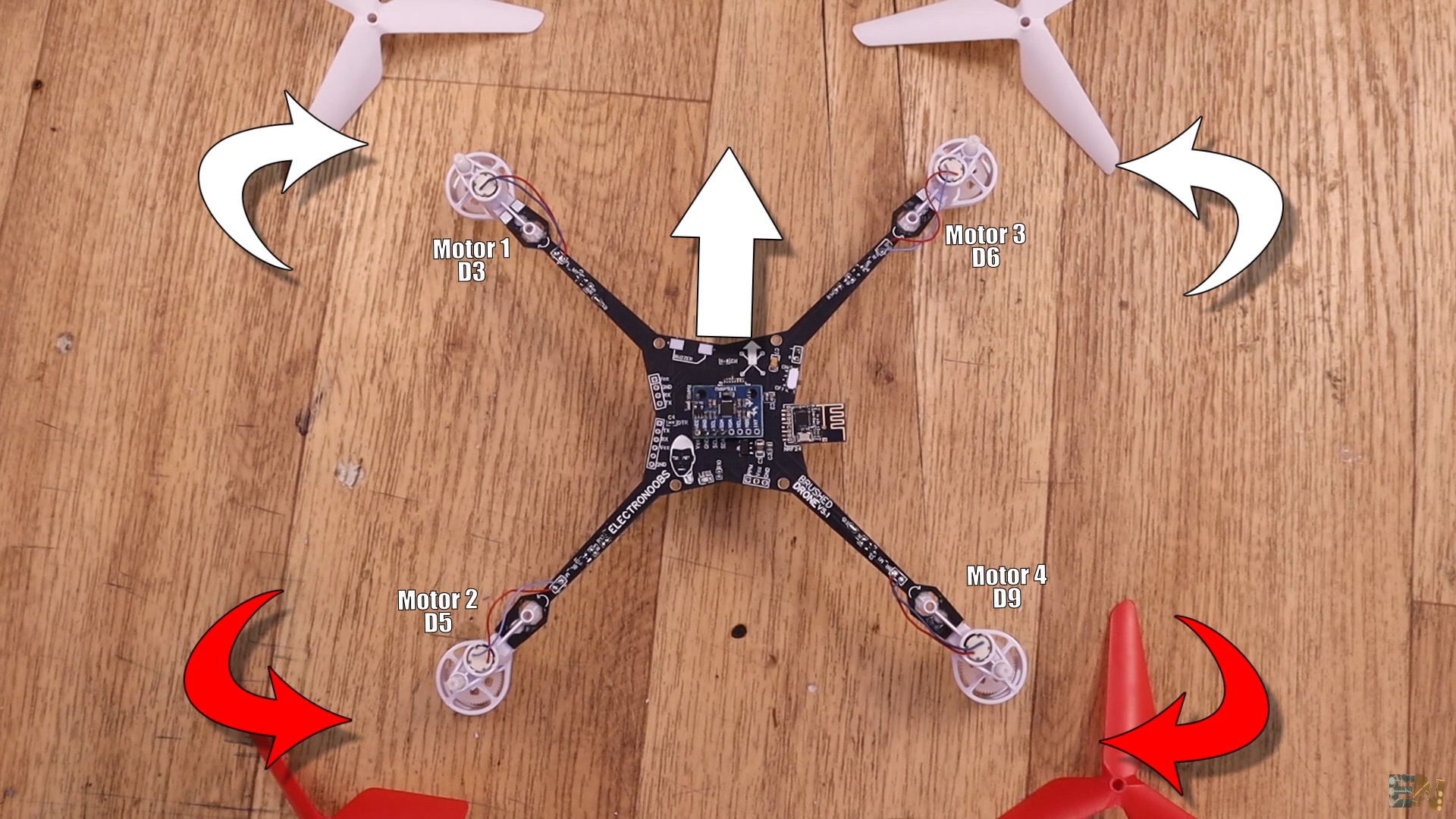
Flip the swith of the drone and radio controller. Flip the AUX 2 swith in order to enable the motors. Then increase throttle and the drone will go up. The better joysticks you have, the better will be the control. Add more sensor for better fly, altitude control and so on. That's it. Consider supporting me on PATREON. Thank you! For any question sue the forum here.


