
 About me
  History
  Let's learn
  Contact us
  Arduino tutorials
 Circuits tutorials
  Robotics tutorials
 Q&A
Q&A Blog
Blog  Arduino
  Circuits
 Robotics
  Modules
  Gadgets
  Printers
  Materials
  3D objects
  3D edit
  Donate
  Reviews
  Advertising


Receiver
You can download the STL files of the Spitfire plane here. Please support me subscribing to my
This tutorial is divided in 3 parts: transmitter, body construction and the receiver.
 3D printed body
 Transmitter
 Receiver
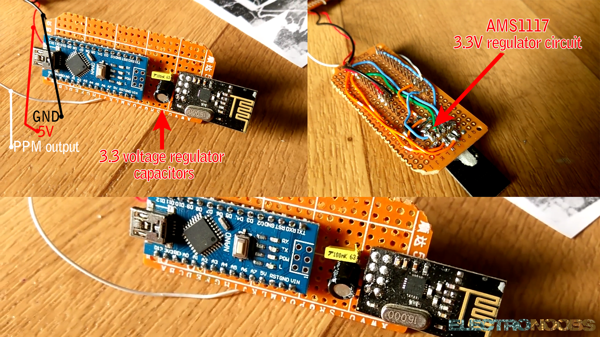
3D printed Spitfire receiver electronics.
First of all we have to create our radio receiver that will receive the 4 values from the radio controller transmitter which are the throttle, yaw, pitch and roll values. To do that we will use an Arduino NANO, the NRF24 radio module, the AMS1117 3.3 voltage regulator, a drilled PCB and some capacitors. You can see the basic schematic of the radio receiver below.
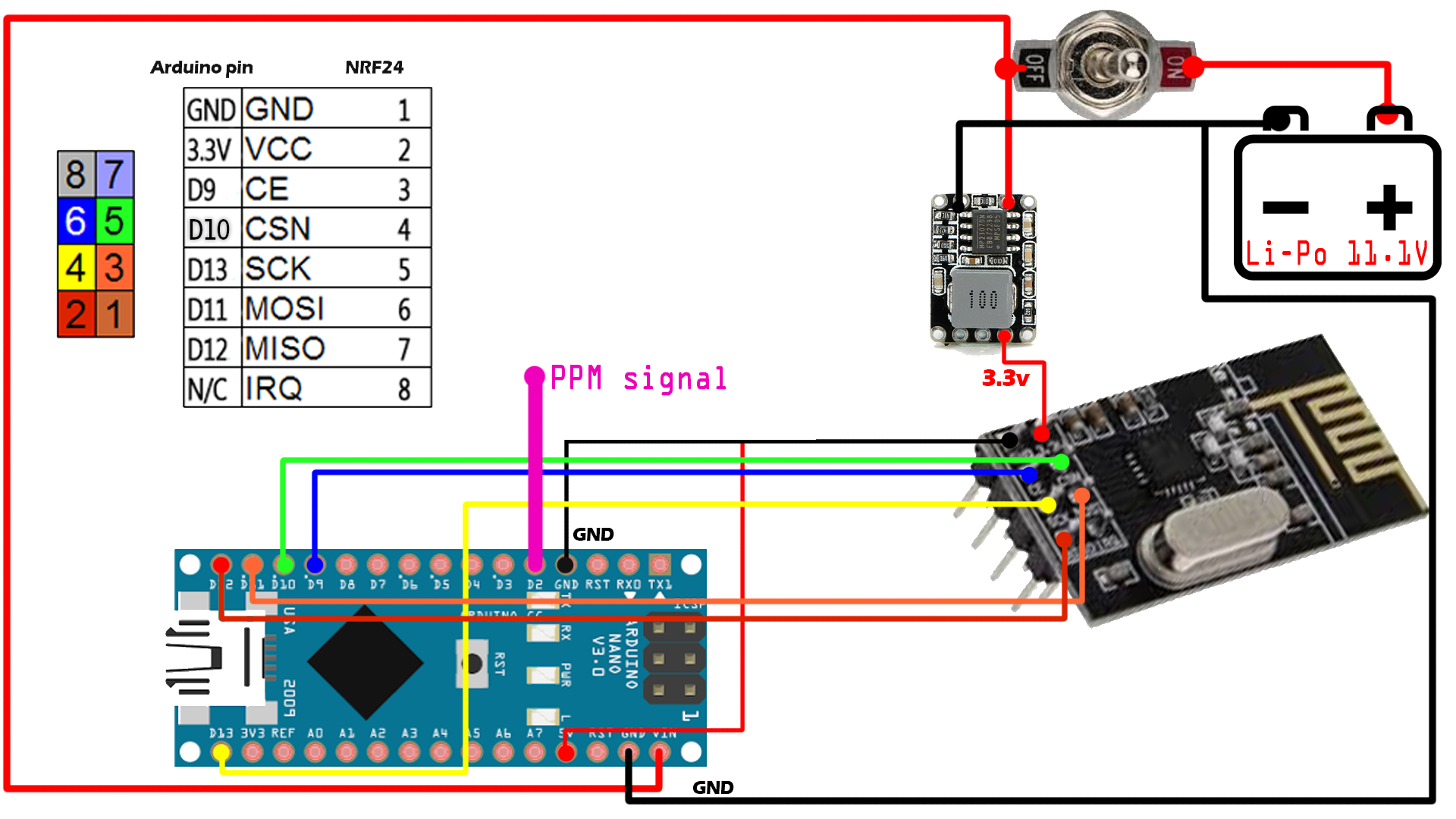
Ok so connect the NRF24 module to the Arduino as shown in the schematic above.
Now we have to program this receiver. To do that download or copy the code below. Also download and install the NRF library if you don't have it. Read all the comments to understand the code. Select Arduino NANO board and upload. The receiver will now receive the 4 channels and send those values using PPM signal to the flight controller which is the next part of this tutorial.
You can download the
You can download the
To install it we just go to Sketch -> Include library and we open the .zip file that we've just downloaded.
/*A basic receiver test for the nRF24L01 module to receive 4 channels and send them using PPM signal. */
/*Like, share and subscribe, ELECTRONOOBS*/

#include <SPI.h>
#include <nRF24L01.h>
#include <RF24.h>

////////////////////// PPM CONFIGURATION//////////////////////////
#define channel_number 4  //set the number of channels, in this case: 4 channels
#define sigPin 2  //set PPM signal output pin on the arduino
#define PPM_FrLen 27000  //set the PPM frame length in microseconds (1ms = 1000µs)
#define PPM_PulseLen 400  //set the pulse length
//////////////////////////////////////////////////////////////////

int ppm[channel_number];

const uint64_t pipeIn =  0xE8E8F0F0E1LL; //This code has to be the same as in the transmitter

RF24 radio(9, 10);

// The sizeof this struct should not exceed 32 bytes
//THIS IS CRAZY, you could sent up to 32 channels of 8 bits each
struct MyData {
  byte throttle;
  byte yaw;
  byte pitch;
  byte roll;
};

MyData data;

void resetData()
{
  // 'safe' values to use when no radio input is detected
  data.throttle = 0;
  data.yaw = 127;
  data.pitch = 127;
  data.roll = 127;

  setPPMValuesFromData();
}

void setPPMValuesFromData()
{
  //Here we map the received values from 1000 to 2000
  //and create the ppm signals for each channel
  ppm[0] = map(data.throttle, 0, 255, 1000, 2000);
  ppm[1] = map(data.yaw,      0, 255, 1000, 2000);
  ppm[2] = map(data.pitch,    0, 255, 1000, 2000);
  ppm[3] = map(data.roll,     0, 255, 1000, 2000);
  }

/**************************************************/

void setupPPM() {
  pinMode(sigPin, OUTPUT);
  digitalWrite(sigPin, 0);  //set the PPM signal pin to the default state (off)

  cli();
  TCCR1A = 0; // set entire TCCR1 register to 0
  TCCR1B = 0;

  OCR1A = 100;  // compare match register (not very important, sets the timeout for the first interrupt)
  TCCR1B |= (1 << WGM12);  // turn on CTC mode
  TCCR1B |= (1 << CS11);  // 8 prescaler: 0,5 microseconds at 16mhz
  TIMSK1 |= (1 << OCIE1A); // enable timer compare interrupt
  sei();
}

void setup()
{
  resetData();
  setupPPM();

  // Set up radio module
  radio.begin();
  radio.setDataRate(RF24_250KBPS); // Both endpoints must have this set the same
  radio.setAutoAck(false);

  radio.openReadingPipe(1,pipeIn);
  radio.startListening();
}

/**************************************************/

unsigned long lastRecvTime = 0;

void recvData()
{
  while ( radio.available() ) {
    radio.read(&data, sizeof(MyData));
    lastRecvTime = millis();
  }
}

/**************************************************/

void loop()
{
  recvData();

  unsigned long now = millis();
  if ( now - lastRecvTime > 1000 ) {
    // signal lost? then reset the data and plane fall down
    resetData();
  }

  setPPMValuesFromData();
}

/**************************************************/

#error Delete this line befor you cahnge the value (clockMultiplier) below
#define clockMultiplier 2 // set this to 2 if you are using a 16MHz arduino, leave as 1 for an 8MHz arduino

ISR(TIMER1_COMPA_vect){
  static boolean state = true;

  TCNT1 = 0;

  if ( state ) {
    //end pulse
    PORTD = PORTD & ~B00000100; // turn pin 2 off. Could also use: digitalWrite(sigPin,0)
    OCR1A = PPM_PulseLen * clockMultiplier;
    state = false;
  }
  else {
    //start pulse
    static byte cur_chan_numb;
    static unsigned int calc_rest;

    PORTD = PORTD | B00000100; // turn pin 2 on. Could also use: digitalWrite(sigPin,1)
    state = true;

    if(cur_chan_numb >= channel_number) {
      cur_chan_numb = 0;
      calc_rest += PPM_PulseLen;
      OCR1A = (PPM_FrLen - calc_rest) * clockMultiplier;
      calc_rest = 0;
    }
    else {
      OCR1A = (ppm[cur_chan_numb] - PPM_PulseLen) * clockMultiplier;
      calc_rest += ppm[cur_chan_numb];
      cur_chan_numb++;
    }
  }
}