About me
  History
  Let's learn
  Contact us
  Arduino tutorials
 Circuits tutorials
  Robotics tutorials
 Q&A
Q&A Blog
Blog  Arduino
  Circuits
 Robotics
  Modules
  Gadgets
  Printers
  Materials
  3D objects
  3D edit
  Donate
  Reviews
  Advertising


Receiver
You can download the STL files of the Spitfire plane here. Please support me subscribing to my
This tutorial is divided in 3 parts: transmitter, body construction and the receiver.
 3D printed body
 Transmitter
 Receiver
3D printed Spitfire Arduino flight controller.
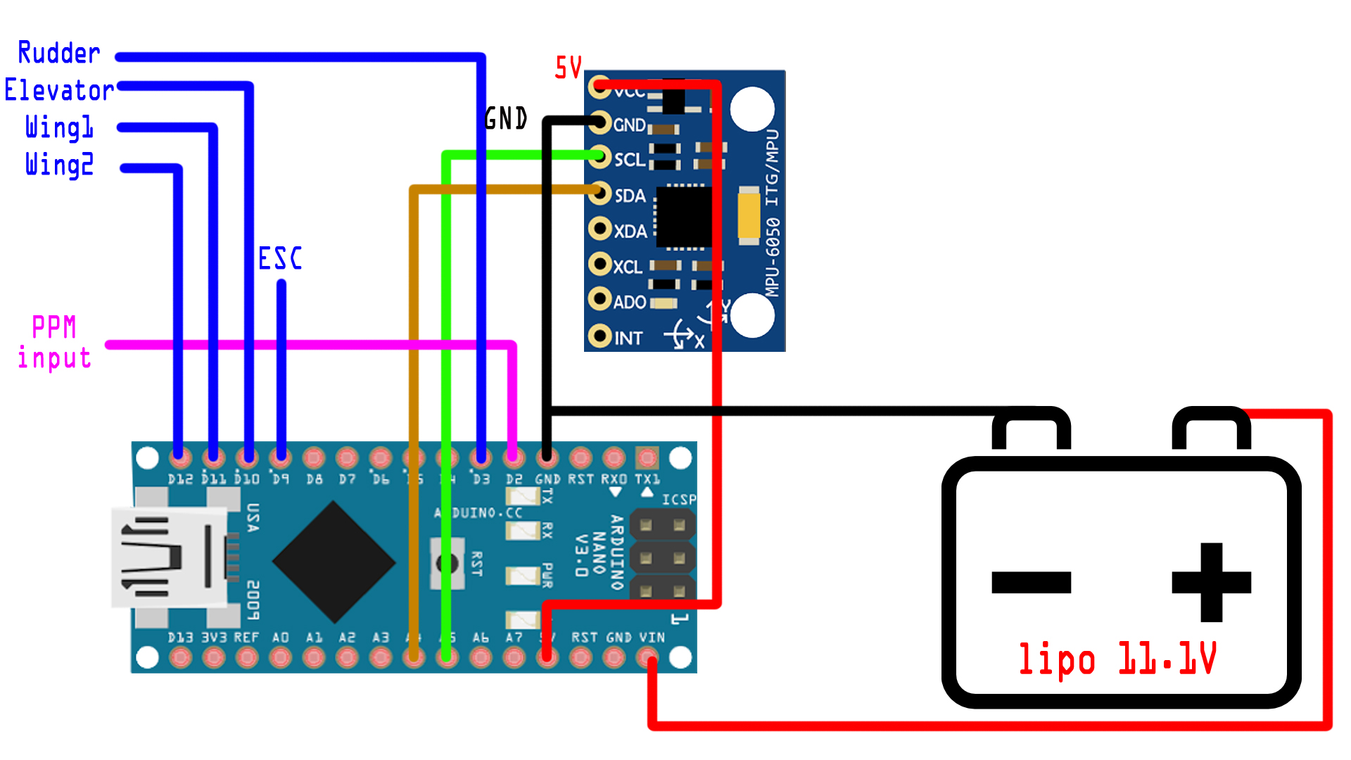
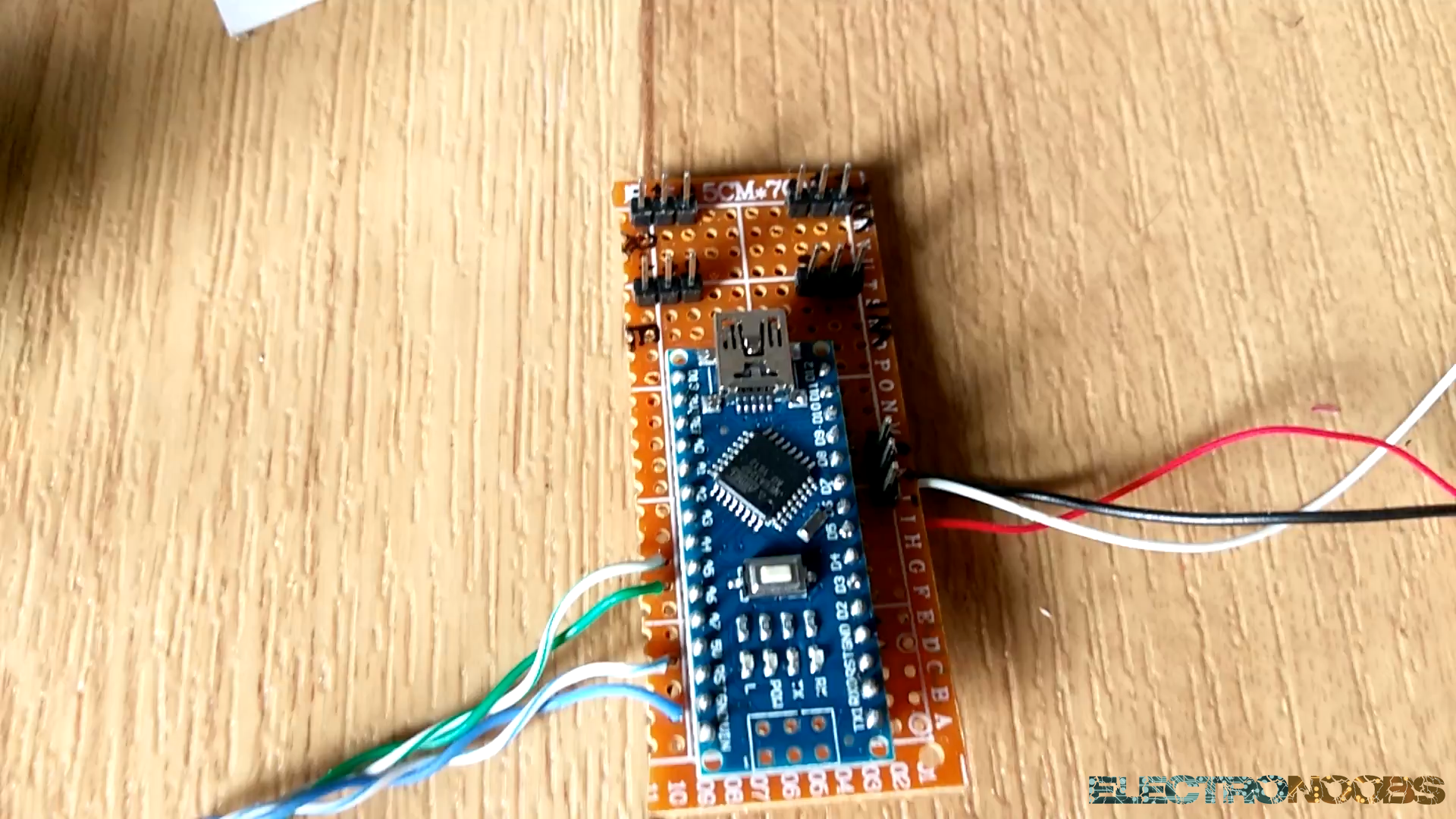
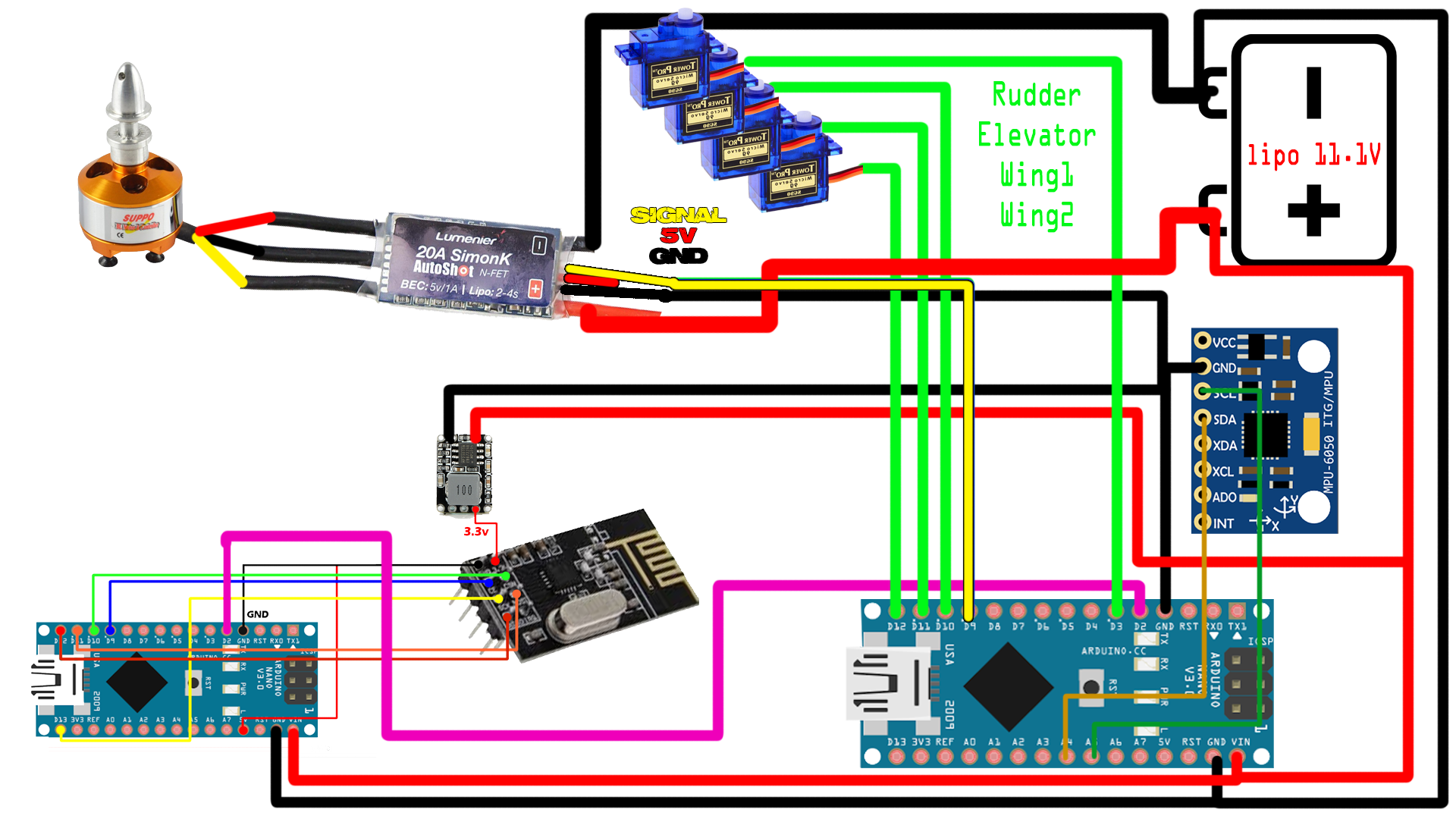
You have two options. Buy directly a Multiwii board or build it. To build the flight controller we will use another Arduino NANO, the MPU6050 module and a drilled PCB. Connect the MPU6050 module as shwon in the next schematic using the i2c serial comunication clock and data to the analog pins A4 and A5 of the Arduino NANO.
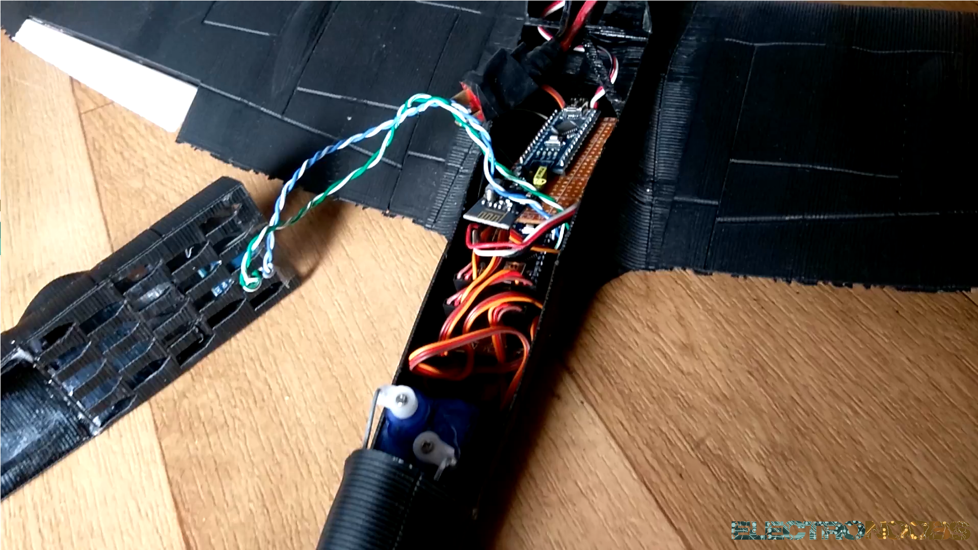
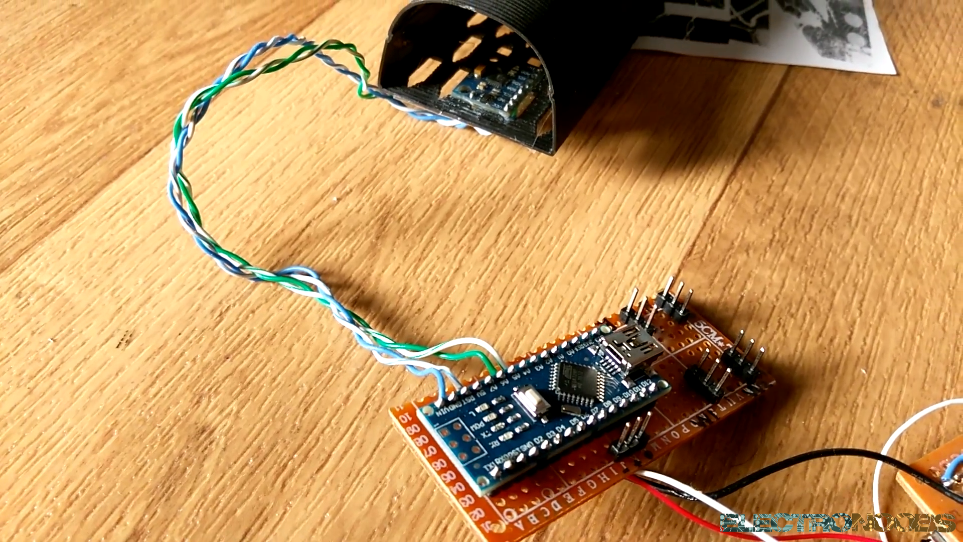
I've also soldered the flight controller arduino to a drilled PCB. I've soldered some pins for all the outputs. Ground, 5 volts and signal pin for the wing1 servo, wing2 servo, rudder servo, elevator servo and the ESC. I've soldered some wires for the i2c comunication of the MPU6050 module. In this way I can glue the module inside of the pilot case so it won't move around. See the final PCB in the next photo.
Now we have to program the flight controller. We will use a platform named Multiwii. Download the Multiwii.zip file below. Unzip the file. There you will find the source code for the flight controller and the JAVA Multiwii platform for 32b and 54b windows. Once you've unziped the file, open Arduino IDE and open the multiwii.ino file from the multiwii source code. This will open a lot of libraries. Go to config.h. There is where we will set all the configurations of outr flying machine.
You can download the
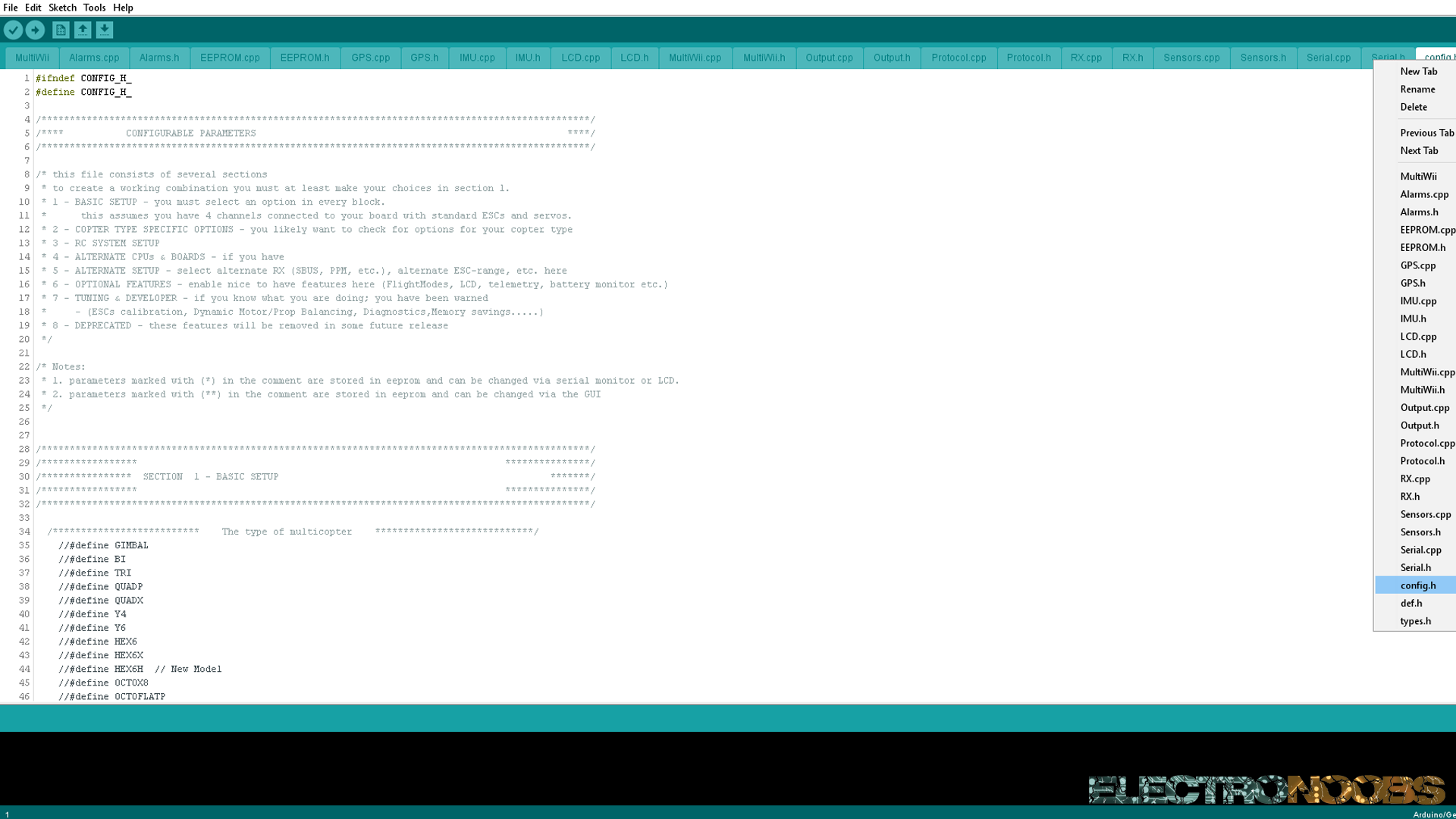
As we can see in the foto above, there are a lot of libraries for the multiwii code. Go to config.h and start change the configuration. To activate a setup just uncoment it by removing the two bars "//". In the type of multicopter select airplane.
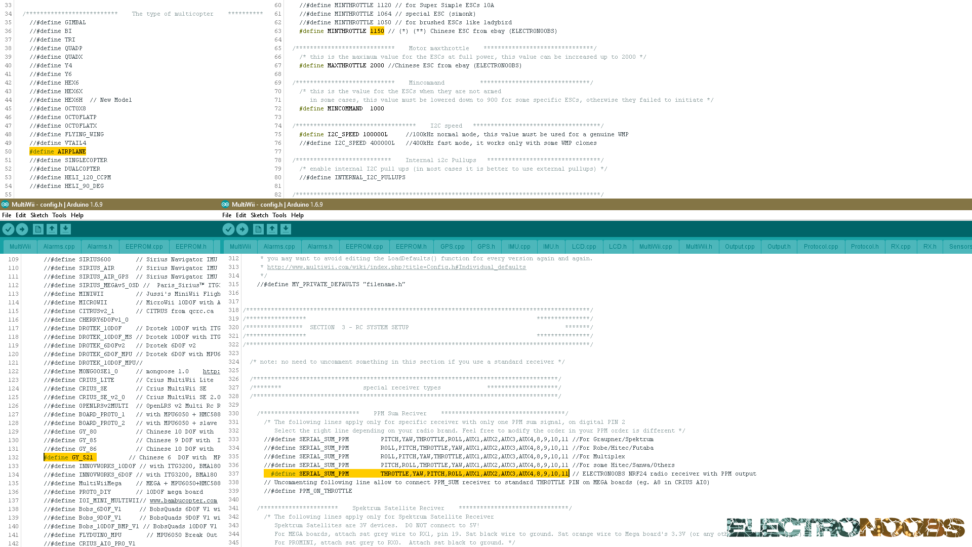
Depending of your used ESC the min throttle and max throttle may vary. In my case min is 1150 and max is 2000. In the Combined IMU Boards uncoment the GY_521 board that includes the MPU 6050module. Next type ctrl+F to open the find tab and type PPM. In the PPM sum setup add this line:
#define SERIAL_SUM_PPM THROTTLE,YAW,PITCH,ROLL,AUX1,AUX2,AUX3,AUX4,8,9,10,11
The code is ready to be uploaded. Select the COM, the NANO board and upload.
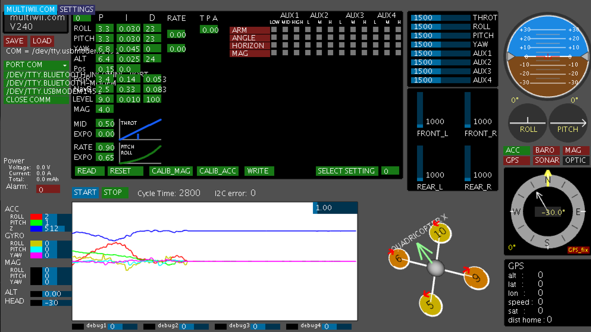
Now open the Multiwii JAVA platform. Select the used COM for the flight controller and click start. You will be able to see the IMU data in real time. You could also configure the plane. After changeing the settings click write to send the data to the Arduino board.
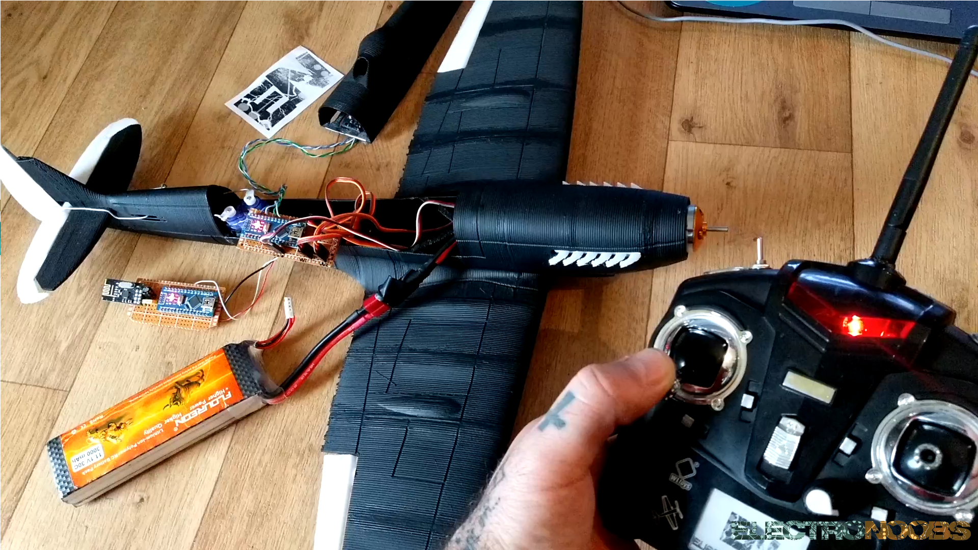
Now that the flight controller is ready connect everything toghether as shown in the next schematic.
Put everything inside the plane, connect the LIPO and start uo your radio transmitter.
The plane is ready to go.