This here is a homemade escape room puzzle tutorial. Meaning that you have to solve all its pieces in order to finish the escape room. Remember that some time back, I’ve made a video on my own escape room based on Arduino and a submarine story. That was a lot of work. Since then, I had a lot of requests for making escape room puzzles. Basically, an escape room is a game, where you have 60 minutes usually, to solve all the puzzles in a room and get out of that room. Well in this case, we don’t have a room. All the puzzles are inside the 3D printed case. This is an easy puzzle, but I would like to start a new video series where I only make escape room puzzles, each time getting harder and harder. I even seen some puzzles on the internet that could cost 20.000 dollars.
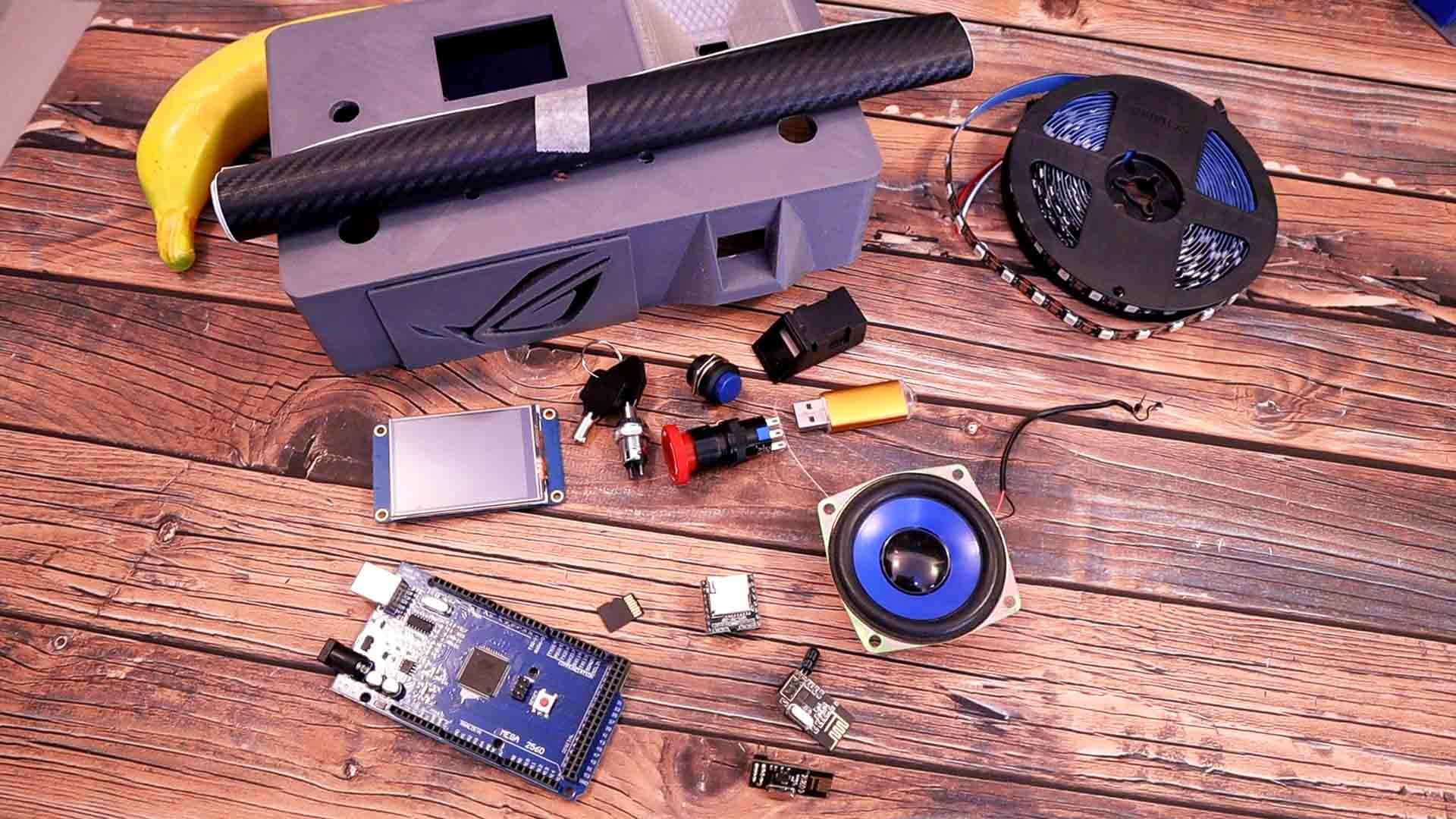
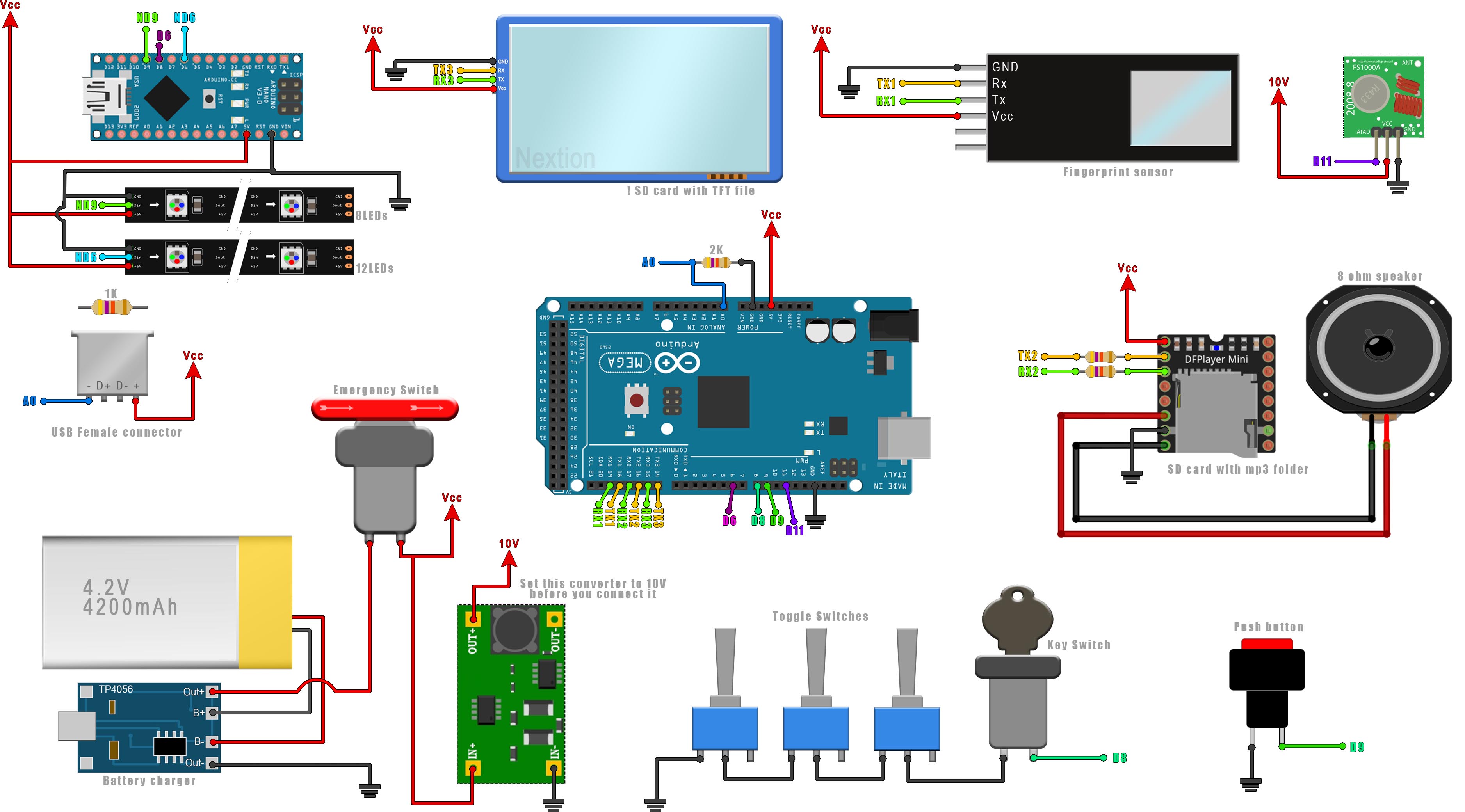
For this project I’ll use a 3D printed case which I will make it look cooler with some carbon fiber vinyl. We need a fingerprint sensor with UART communication, a big push button of any color, we need a key switch, a broken USB adaptor that is very cheap, an emergency switch, the NEXTION touchscreen display of 2.8", a DF player in order to play sounds, a micro SD card, a speaker. And for RGB colors we could add some WS 18 12 LED strip. To control everything I'll use an Arduino. Since I need more memory, I'll use an ARduino MEGA. To send the final data I will use an 433MHz radio mdoule but you could use a simple wire or any other radio mdoule. To supply this we could use a fixed supply, but in my case I want this to be portable so I’ll use a 4.2V battery. We also need 3 toggle switches. You have the connection schematic back on the tutorial page.
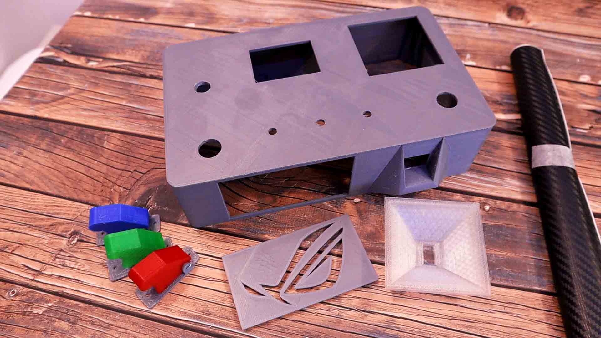
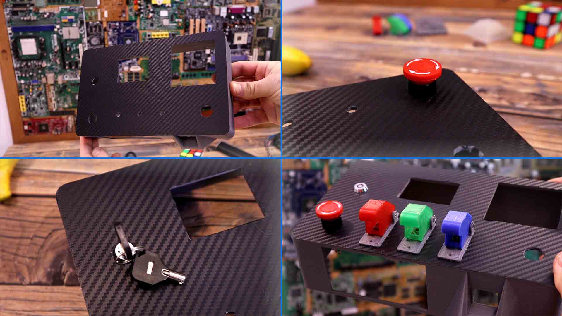
We start by preparing the 3D case. So go below and dwonlaod all the 3D STL files. Print them without support with 3 perimeters, 0.2mm layer height and 15% infill. Also print the covers for the toggle switches and I've printed the side rectangle part with the ASUS ROG logo because I'll give this case to my brother to use it with his PC. So get the case and the carbon fiber vinyl. Measure it and cut it to size more or less. Glue the vinyl and make sure is well stretched. Then flip the case and cut the excess to size. Also cut the holes for the screen adn buttons. Now the case looks a lot better. We could now add the buttons.
I first add the emergency switch on one corner. Next I do the same for the swith key. I make sure that the arrow is pointing upwards so the key will rotate at 90 degrees with the case. Next we add the toggle switches. For that first connect the 3D printed covers with a metal wire or you could directly buy switches that already have the cover. Then we add the swtich followed by the cover. You could also add some gule. Tight the nut and that's it. We have the toggle switches.
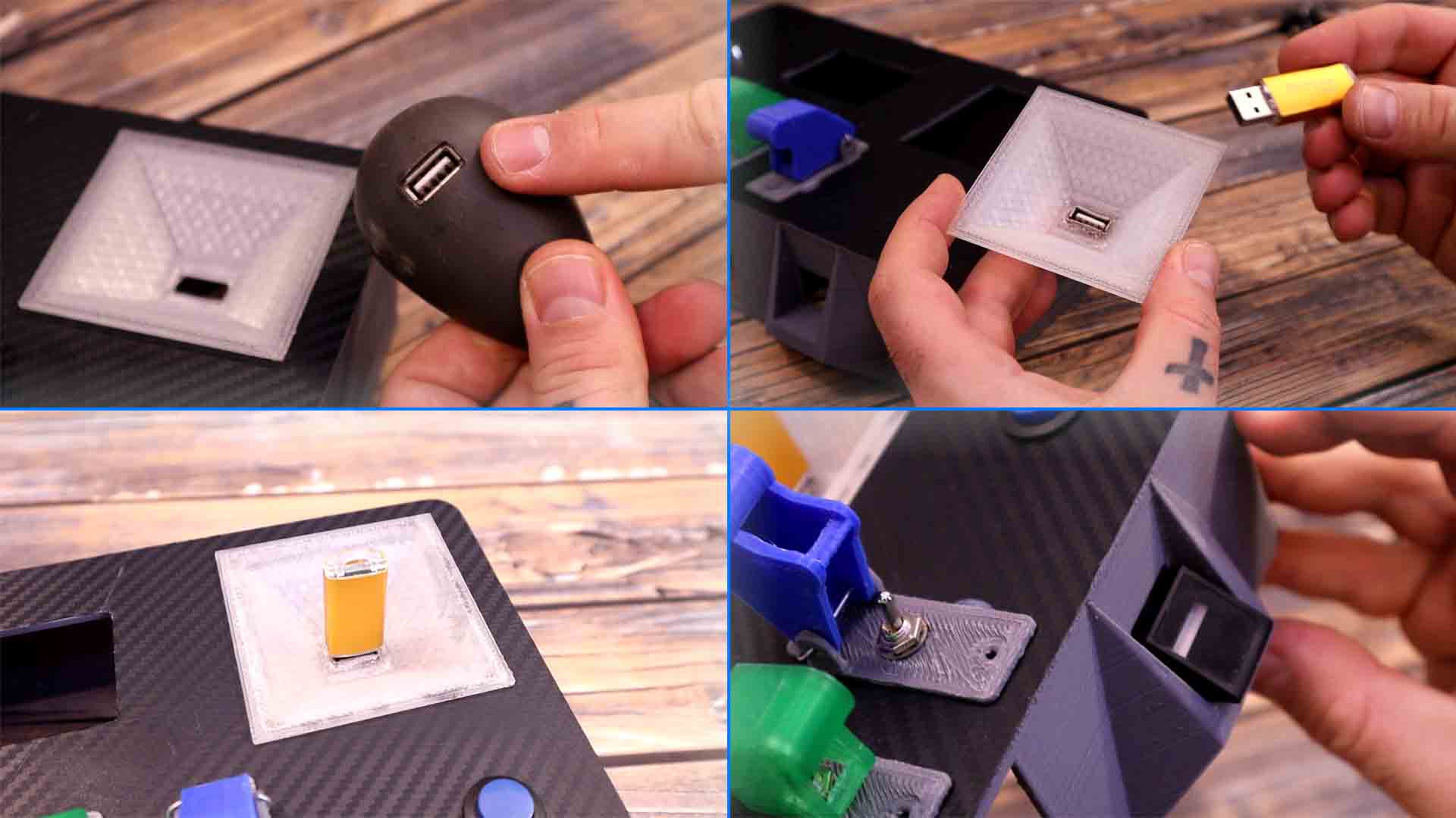
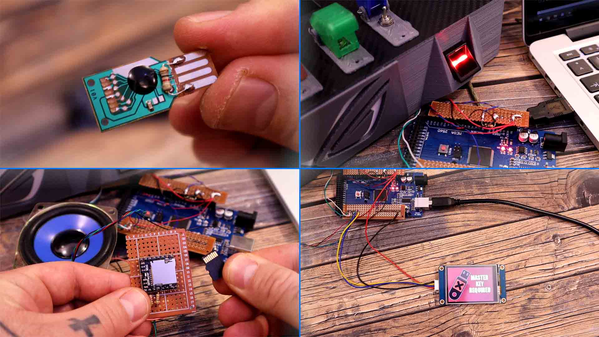
Next I add the part for the USB drive that will be on the transoarend 3D printed part taht looks like a cone. For the USB connector I will take it out from an old adaptor. I tear down the adaptor and take the connector. Then I glue it on the 3D printed part. Now we could insert the USB drive. After I solder two wires to the USB connector I glue the part on the case. Next we need to add the fingerprint sensor. That will go here on the side hole. We have to push it in and glue it. All is left is to glue the NEXTION display in the middle but I'll do that later after we make some tests and I'm sure everything works.
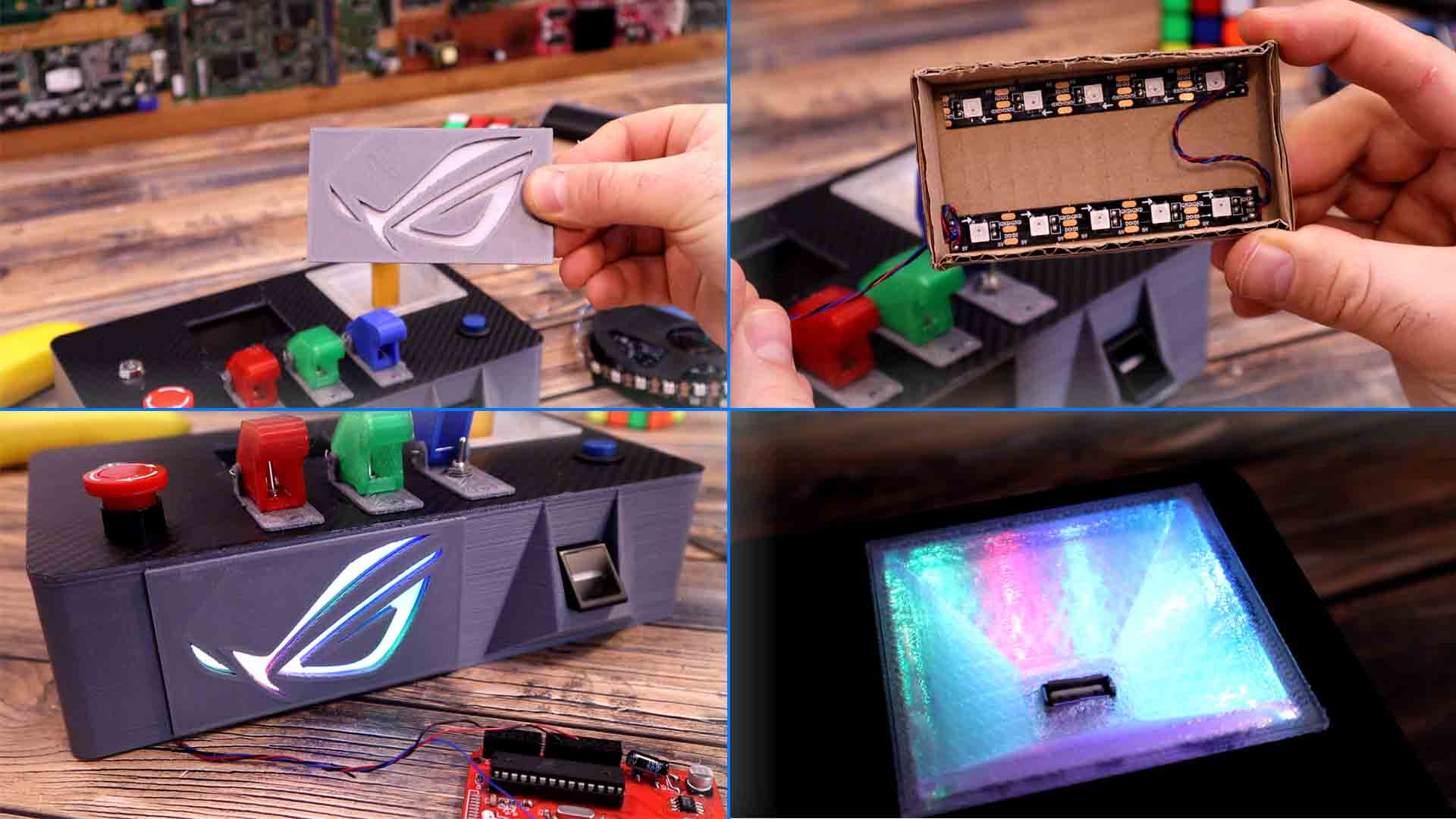
Next I want to add RGB LEDs to the LOGO and behind the transpared 3D printed part. First I glue a white paper behind the logo part. That will difuse the light. Next I make a small case out of carboard and I will glue the LEDs there. I solder wires and glue the LEDs inside the case and make sure you fillow the data arrow on the strip. Now I can glue the logo on the main case and then add the cardboard box with the LEDs behind. After I glue them, I connect it to my Arduino and uplaod an example sketch, and i have to say, it looks quite good. I then also glue another LED strip on the inside of the case so the light will shine through the transparent USB drive. I upload another test code and again, it looks quite good, we can now make some light effects as well.
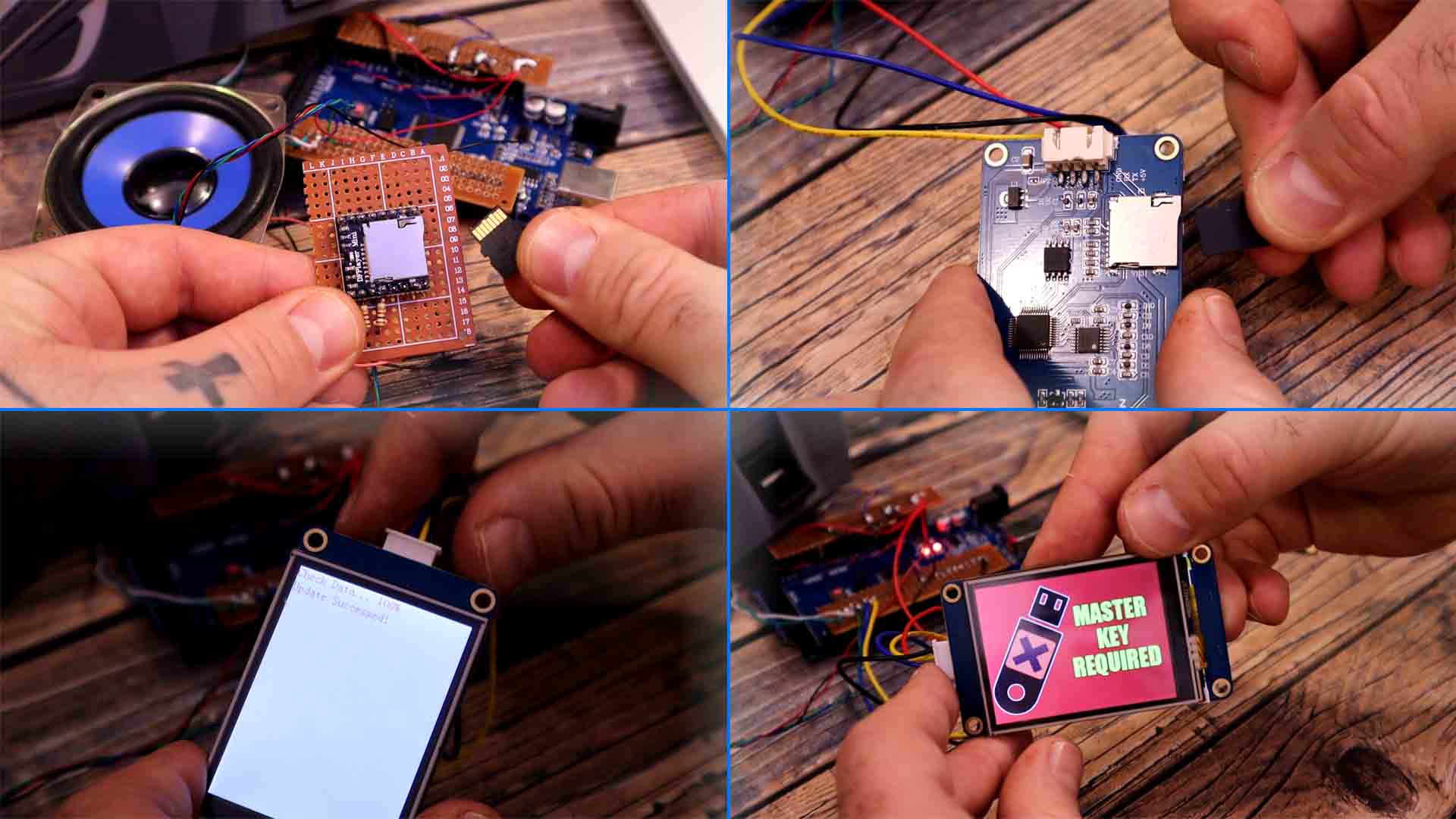
Before I add the rest of the electronics and make the connectiosn for all the buttons, you have to know how each part will work. First the USB drive key. What I will do is to palce a resistor inside the USB adaptor. Then, inside, connected to the Arduino, I will have another resistor connected to analog input A0. These two will create a voltage divider and the voltage will have a certain value. So all I have to do in the code, is to measure the voltage and if it is in the desired range, then we have inserted the good USB key. As for the other parts, you have the links below for each module. One for the DF player, the Nextion display and the fingerprint sensor.
Ok so, everything works. I'll make the connections inside the case. As you could see in the video, we have a lot of wires. Check the final schematic below. Finally, I've placed a second Arduino NANO, that will only control the RGB LEDs. Havin two RGB LED strips on top of the other code was too much for the Arduino MEGA. I mean it could do it but we would have a lot of delays. So now the LEDs are controlled by the Arduin NANO. For the battery I have a samsung 4.2V connected it to the UBS charger and protection module. The Arduino, the modules and the display are working perfectly with voltages above 3.5V so we can use this battery directly. The voltage from the battery is connected to the emergency switch and that will turn the entire system on and off. FInally instead of tge NRF24 module I've used other radio trasmitter, because is easier to use, the 433mHz module. To increase it power we need to use it at more than 5V so for that I have a boost converter module that will increase the voltage only for the radio transmitter up to 10V. This will send an OK when everything is ready and we push this button. The receiver will detect that OK and do something, for example turn on a PC, a LED, a relay or whatever you want.
We have multiple files for this project. You need to download from below the mp3 folder and paste that to the SD card of the DFplayer. So format the SD card and unzip the mp3 file form below. Make sure you copy the entire mp3 folder to the SD card and not jsut the mp3 files. Then go adn downlaod the TFT file for the Nextion display. Get another SD card and format it to FAT32. Copy the TFT file to the card and insert it into the Nextion display. Then power the screen up and you will see that the TFT file will be coppied to the display memory. When you get 100%, power off the screen and remove the card. Power back the screen and you will have the TFT file working.
We have 2 codes for this project, one main code for the Arduino Mega and another code for the small NANO taht controls the LEDs. We also need multiple libraries for the DFplayer, the fingerprint sensor and LED strip.
#include <Adafruit_Fingerprint.h>
#include <RH_ASK.h>
#include <DFMiniMp3.h>
Please read more in the code. I hope that you like this video and more important, that you have learned something new. If so, maybe give a like the video below and consider subscribing. If my videos help you, consider supporting my work on my PATREON or a donation on my PayPal. Thanks again and see you later guys.