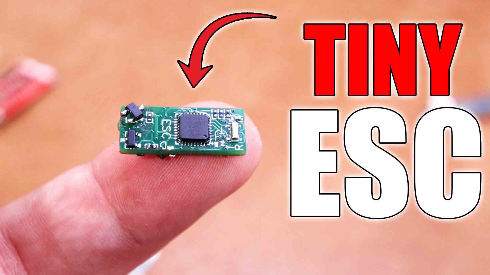
This is my design of probably the smallest ESC for triple phase brushless motors you can find out there. It is only 8mm wide and 2 cm long. But is it perfect? Yeah, it is, obviously. Nah guys, just kidding. It still has some small errors but it works almost as I expected. As you all know I’ve made a lot of ESCs on this channel, and my last version works as any other commercial ESCs reaching very high speeds. But I wanted to make a smaller version, the smallest I could possibly make it. So this time the circuit is a lot simpler, I’ve used very small components that could still be soldered by hand and I've also made a 4 layer PCB. So let me take you to my journey of making a few versions till it finally worked so you could also learn how to make one. So guys, let’s get started
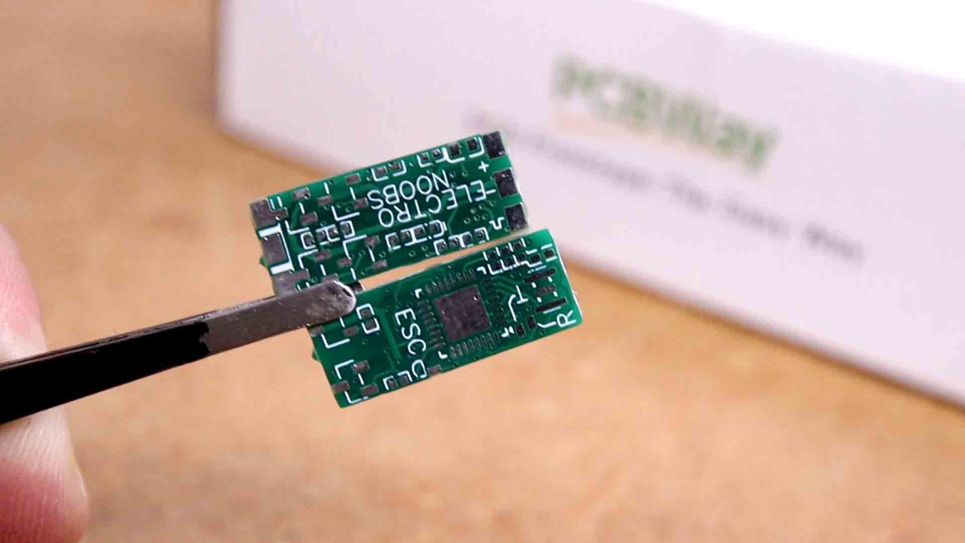
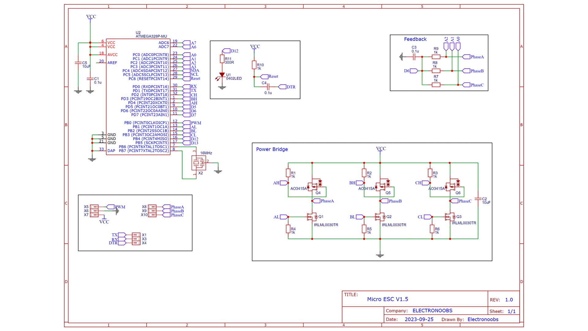
This PCB is as simple as having a microcontroller with a 16MHz resonator, programming pads, 3 P-Mosfets and 3 N-Mosfets. The rest are just simple capacitors and resistors for pulldowns and pull ups, because everything is done in the- code. All size are 0402 (except some capacitors of 0603) which I’m still able to solder by hand. My first version was using 0201 resistors and capacitors as you can see on this other PCB, and since it was very difficult to solder, I’ve ordered a new version. The second version which has a purple PCB int this case, had a different problem with the feedback resistors. Finally, this is the last PCB, which still has a small error, but at least I know it works and let’s see how. This is the schematic. The ATmega328p microcontroller in a QFN package so it occupies less space. The triple phase bridge with P and N mosfets. The power input pads, the pads for programming and the phase out pads. Finally we have some resistors for the feedback detection.
Let’s start with the part list. Well, is very simple: The microcontroller, the MSOFETs, resistors and capacitors, a small LED and that's it. Also, you could order a small brushless motor to test it out. Extra, you need the FTDI programmer for uplaoding the codes.
The PCB I’ve made for today's project is only 8 mm wide, as you can see in in the video on the tip of my finger. The reason I have it in multiple colors is because this is the third version, because believe it or not, even if the circuit is simpler, the project got more difficult because of that. If you want to try the same project, you could download my final GERBER files from below and try it out, maybe you could improve it. Go to PCBWAY.com and click the quote button and on this next page add the settings such as size, amount and color. In this case this is a 4 layer PCB so I also select that option. Save to cart and on the next Page I upload the GERBER files. Place the order and in a few days, receive some very very small PCBs. They look great as always, so let’s get started.
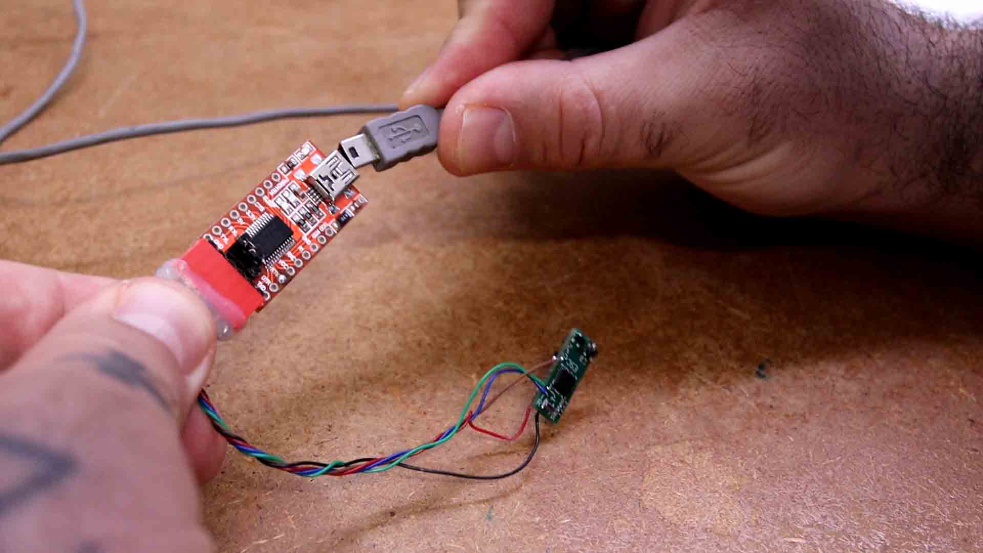
Ok now, to make it faster, I’ve taken my ATmega chip from an old Arduino clone. In that way I know for sure it has a bootloader. First I’ve solder the chip, the resonator, the reset pullup and the DTR capacitor so we could test it. I’ve tested if the microcontroller works using one of these FTDI programmers. On the PCB I have the R, T and D pads corresponding for RX, TX and DTR. For Vcc and GND you could use the power input pads. Once I know it works, I solder the rest starting with all the 0402 resistors. Soldering these small components by hand is not that difficult. Just have some patience and is a bit easier using soldering paste. Then I’ve added the MOSFETs one by one.
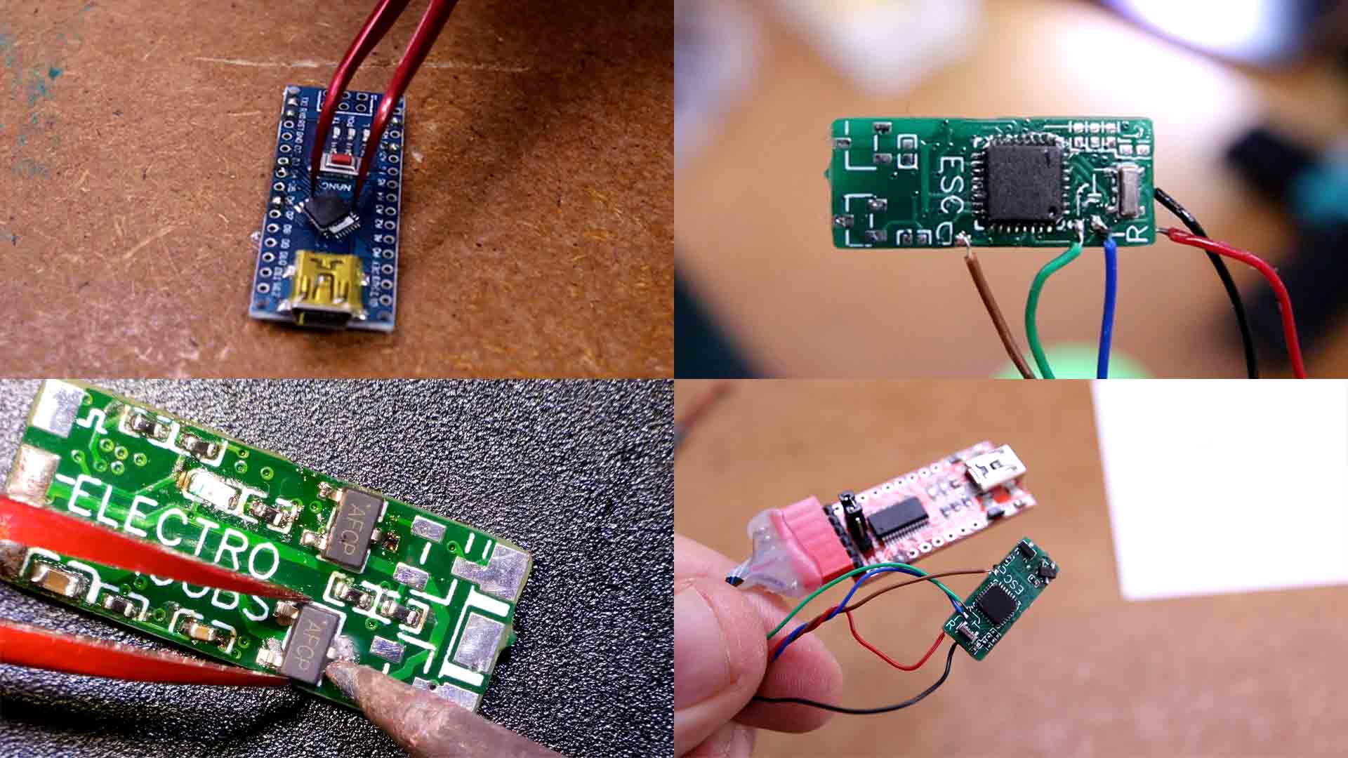
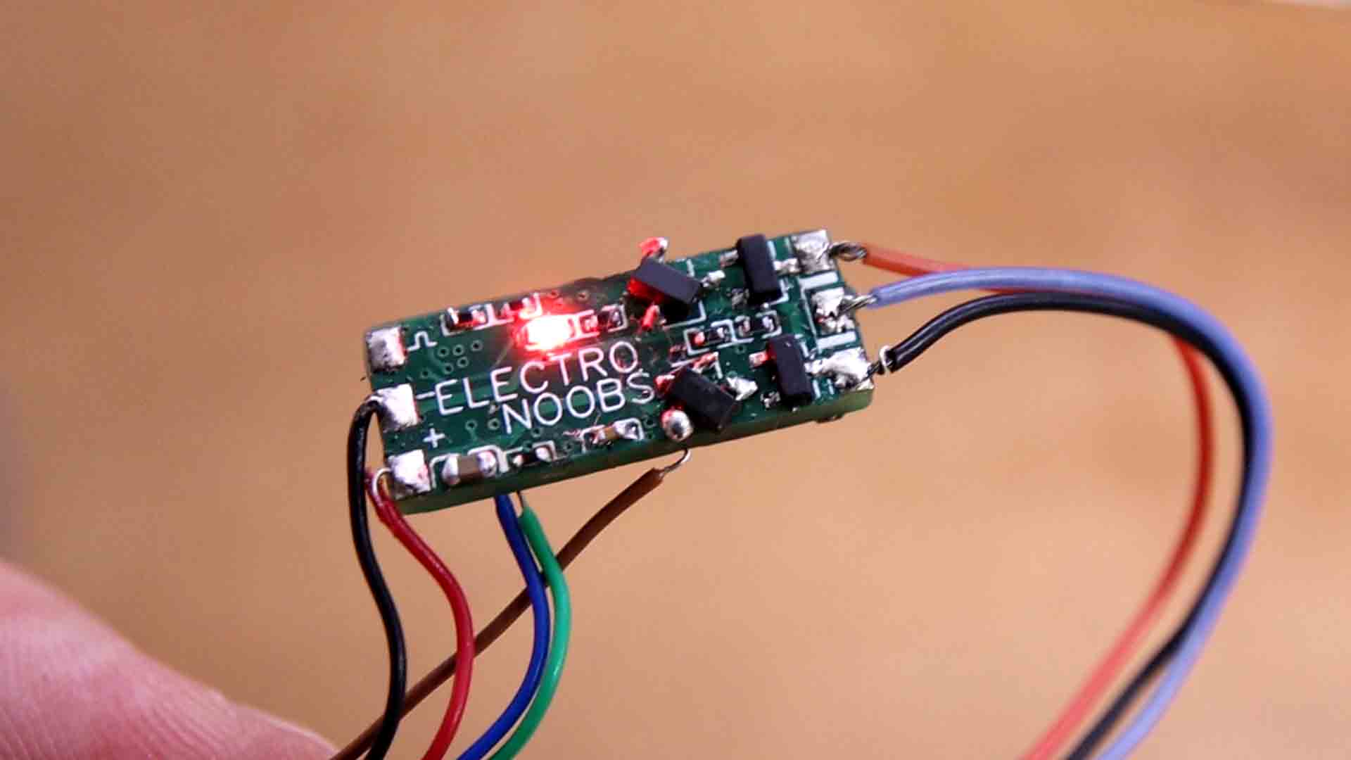
Not that it is ready, I wanted to test it so I’ve connected a small brushless motor one at the output. But as you can see in the video on this thermal camera, some mosfets were getting hot. That’s because the P MOSFET I’ve used on the PCB design has the source and drain pads reversed. That’s the error I mentioned at the beginning. (Don't worry, the error was fixed on the GERBERs you download) That’s why, finally I’ve soldered 3 of the MSOFETs like you can see in the video. It looks ugly but at least I can test it. Having this thermal camera helped me a lot to find out which component was failing.
I use the FTDI programmer to upload the code. If you check the code, you will see that we use PC INT interruptions on pin D8 to read the PWM input. Then, this is the comparator interrupt on pin D6. That’s where the feedback zero cross is connected as you can see in the schematic. Depending on the feedback, we change to the next part of the sequence. We have these 6 steps of that sequence. And depending on the step, we activate the pins that go to the MOSFET bridge, and that’s it. I upload it and I do some tests.
I had to tweak some variables for the ramp up part in the code but it finally worked. I use this servo tester to control it. I connect it to the ESC and at the output I add one of these very small brushless motors. It can’t work with big motors since the maximum current would be around 2 amps or so. I power it at 5V and no more than that, or it would burn the chip. And there you have it.
It can reach a descend speed. Here I measure the speed. It reached 16 thousand RPMs which is amazing.
I can’t measure the torque right now because I don’t have a setup.
Now, is this working perfectly? Well, No. That's because during tests, it was resetting all the time. I think it is because of the current peaks. I’ve added a capacitor at the input and that improved the working time but even so, after some minutes, it resets. Obviously, I have to fix that since I would not rely on an ESC that might fail at any moment. Also, the ATmega328 is quite sensitive to voltages input fluctuations so maybe using a different microcontroller would be better.
If my videos help you, consider supporting my work on my PATREON or a donation on my PayPal. Thanks again and see you later guys.