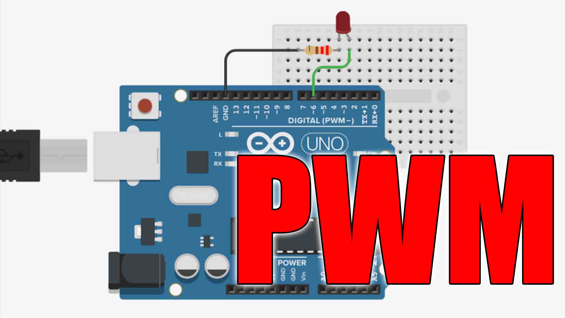
The 8-bit PWM output of your Arduino will work fine in many cases. Particularly with motors and LEDs for controlling speed or brightness. However, what if you must have an actual DC voltage not just PWM pulses? This tutorial will show you how to create that analog voltage using an LM358 or any other simple OpAmp along with a resistor and a capacitor that will create a low pass filter. Now, I’ve attempted to give you a functional description of the circuit, not only to aid you in understanding, but also so that you get a sense for how you may wish to tweak it.
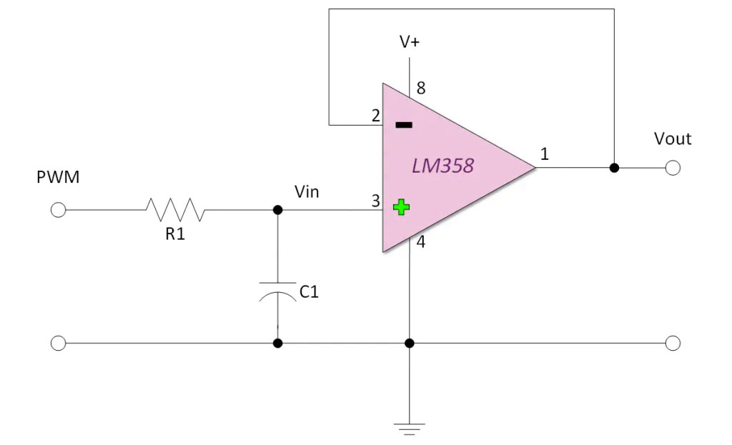
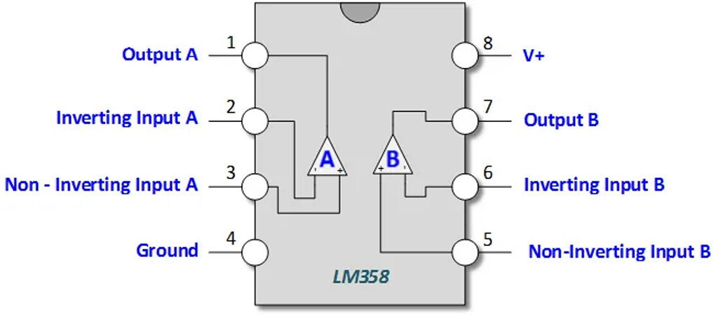
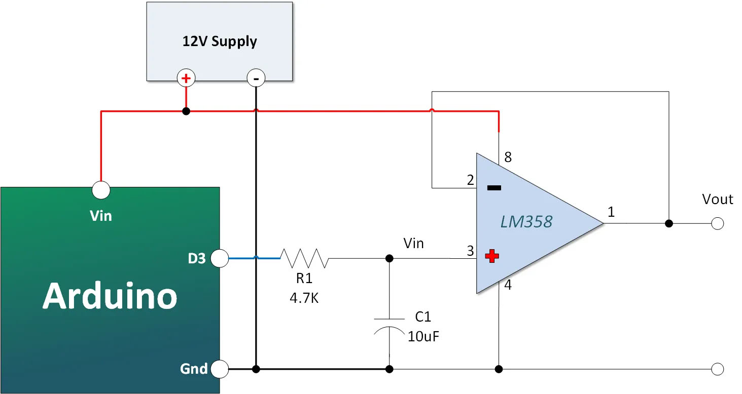
The circuit presented uses an LM358 Op Amp in a Non-Inverting Voltage Follower configuration. If you’re unfamiliar with Op Amps, you can read an easy to follow description HERE. It also uses resistor and capacitor in series to form an RC time constant that charges to the desired voltage. You could omit the op amp, but it has some advantages. For one, it has a nice high input impedance. Second, it offers a degree of protection for your Arduino.
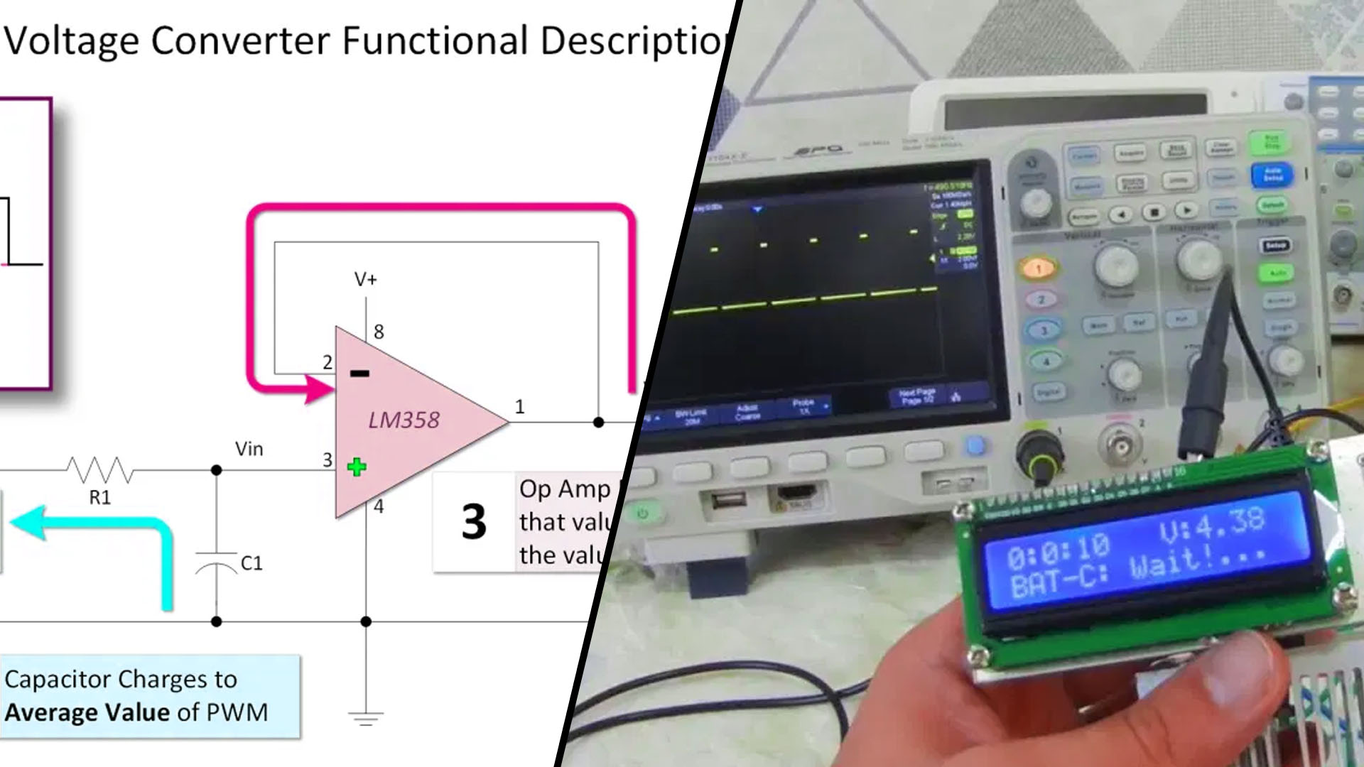
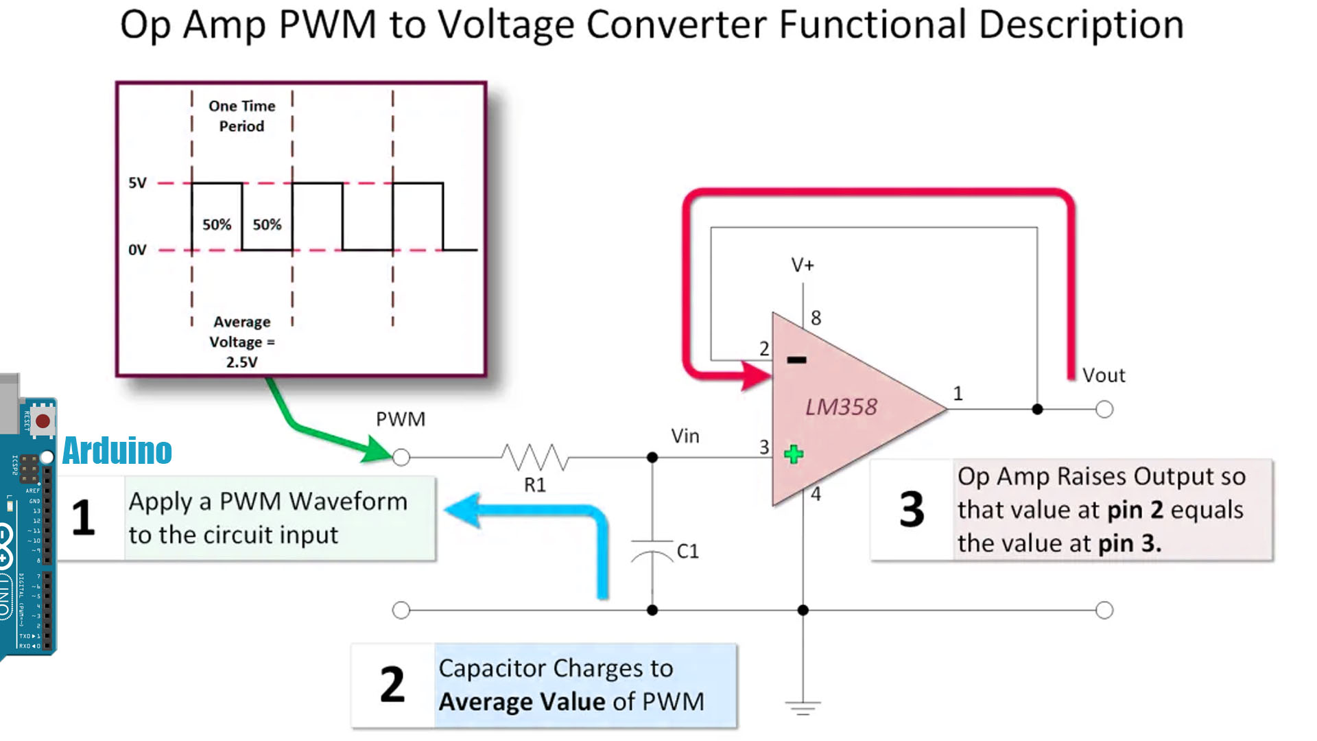
The image and text below serve to give you a sense of how this circuit works.
1) A PWM signal is applied to the input of the circuit. Pulse width modulation has few characteristics that are important to us. The first is the period of the signal. That is two say, how frequently the PWM signal repeats itself
Next we’re interested in the amplitude, or how high the signal goes in volts.
Finally, we want to know the percentage of time the signal is on.
2) Next, the capacitor C1 charges through R1 to the average value of the capacitor. The time it takes to charge to this value is determined by the RC time constant. The values for the capacitor and resistor are largely driven by the time period of the PWM. Another consideration in resistor selection has to do with maximum current handling capability of the Arduino Output. The capacitor should also have a voltage rating that is higher than the voltage it is expected to charge to.
● One time constant in seconds = Value of Resistor in Ohms x Value of Capacitor in Farads.
● It takes five time constants for the capacitor to charge very close to 100 percent.
3) Finally the Op Amp responds by raising or lowering its output until the value at pin 2 ( the inverting input) is equal to the value at pin 3 ( the non-inverting input).
C1 and R1 in our circuit are in a configuration that is know as a low pass filter. That means it is designed to pass lower frequencies while blocking higher frequencies. More it establishes a time constant that allows us to charge to the value of our Arduino PWM output.
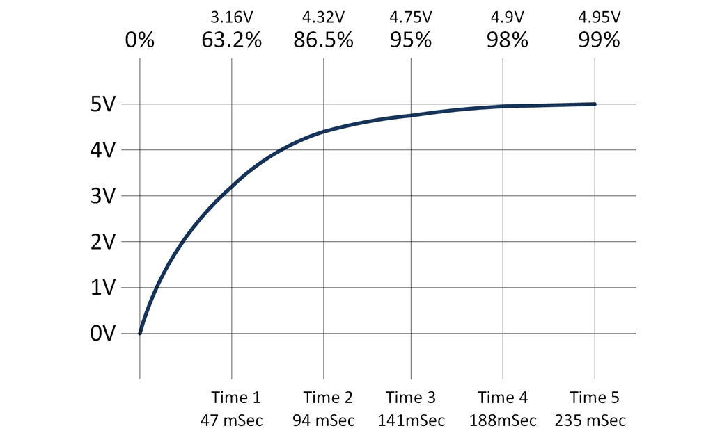
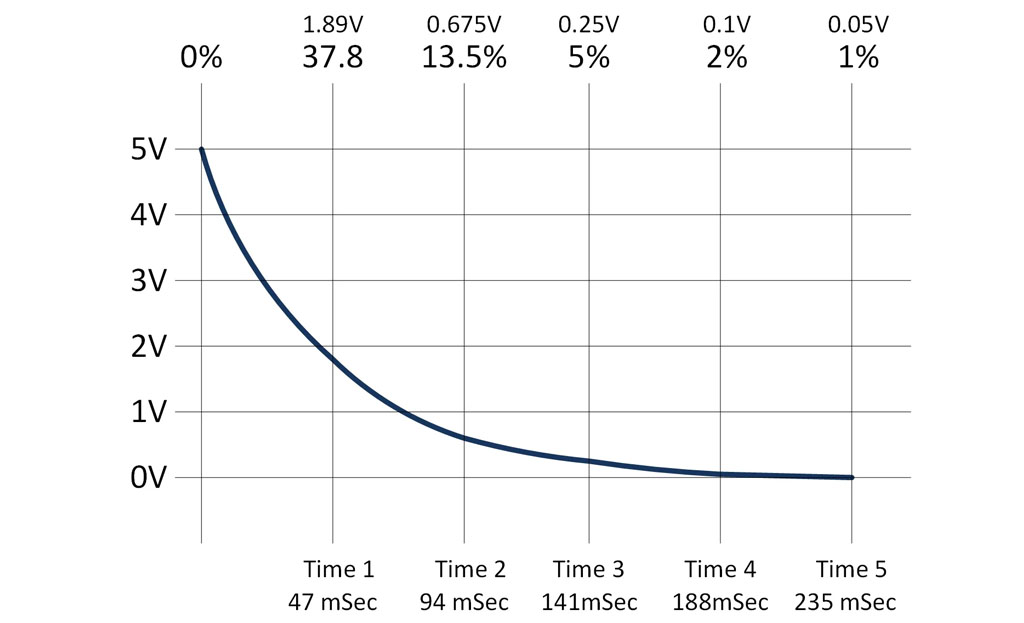
To get a sense for how the low pass filter interacts with the PWM, it also useful to look at the discharge time constant. The curve is the inverse of the charge curve.s:
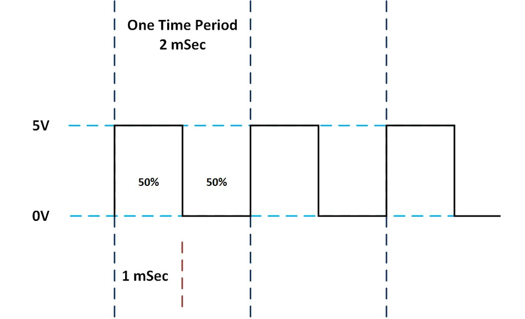
There are two default frequencies in the Arduino Uno PWM. One is 490 Hz and the other 980 Hz. I’m using a digital PWM pin with a 490 HZ output. The time it takes for it to complete one cycle is determined by calculating the inverse of the frequency:
Time in Seconds = 1 / Frequency in Hertz
Therefore the period is 1/490 or approximately 2 mSec. If we select a 50% duty cycle, the timing will look something like this:
So we have a capacitor that takes 235 mSec to charge and PWM that is only on for about 1 mSec. One the surface, you might conclude that it will never charge up. However, if you examine the charge and discharge curves a little closer, you will see that it does charge (albeit slowly) in a pattern that looks like a warped stairway.
You will want to use a common external supply that is greater than 5V. A 9 volt supply would work. If you try to power the Op Amp with 5 Volts will cap your output voltage to about 3.6 volts.
Copy Paste and Up Load the Arduino PWM to Voltage Out Converter Sketch. The sketch is really basic. You’re going to cycle through various voltages in three second intervals. Connect a meter to your pin one on your LM358. If you observe it long enough, you will see it march through the programmed values.
int pwmOut = 3;  // The output to the transistor that drives the motor

void setup()
{
  pinMode(pwmOut, OUTPUT);
}


void loop()
{
  analogWrite(pwmOut, 0); // about zero volts
  delay(3000);
  analogWrite(pwmOut, 51); // about 1 volt
  delay(3000);
  analogWrite(pwmOut, 102); // about 2 volts
  delay(3000);
  analogWrite(pwmOut, 128); // about 2.5 volts
  delay(3000);
  analogWrite(pwmOut, 153); // about 3.0 volts
  delay(3000);
  analogWrite(pwmOut, 204); // about 4.0 volts
  delay(3000);
  analogWrite(pwmOut, 255);  // about 5.0 volts
  delay(3000);
}