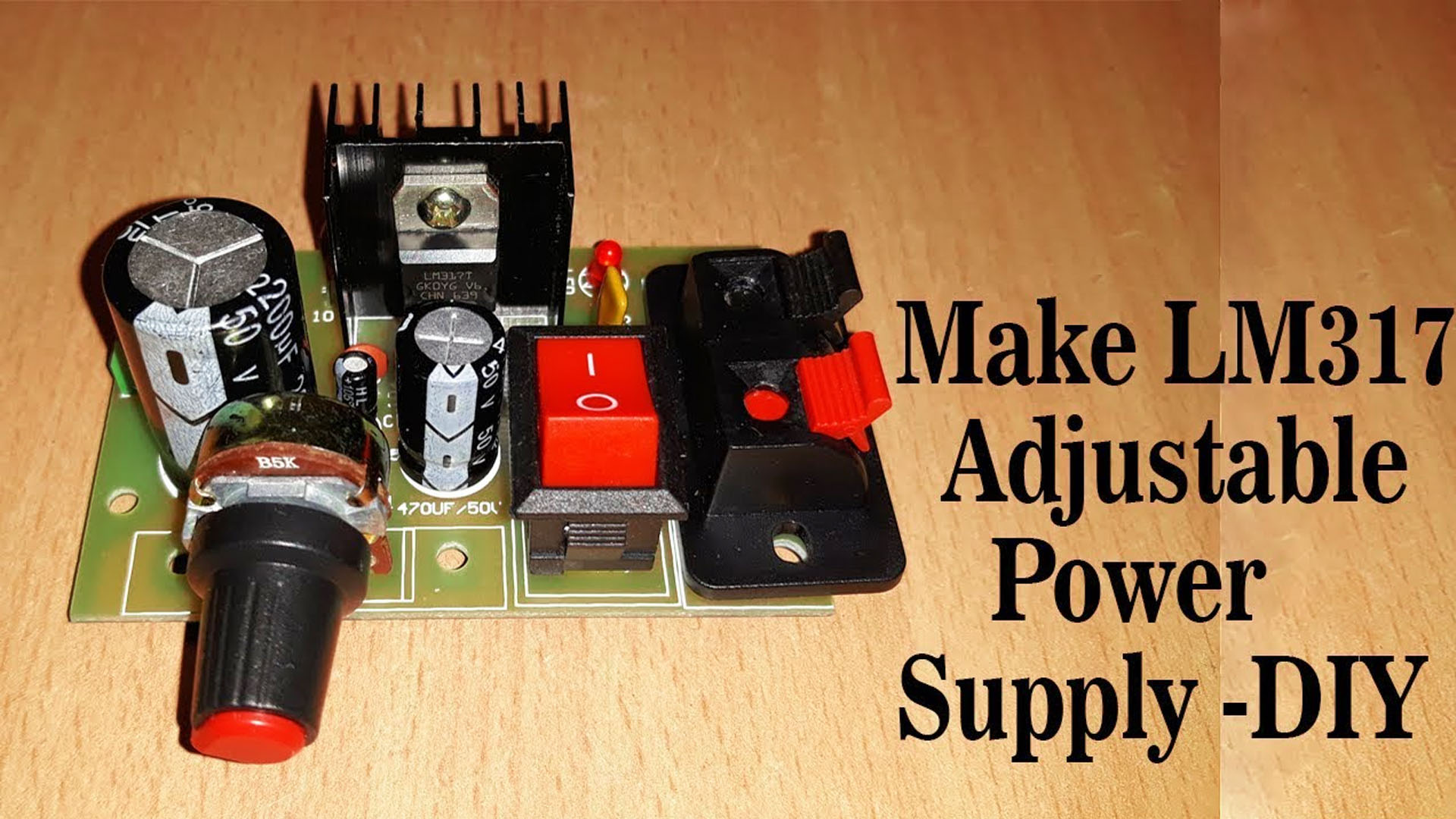
Hello everyone! I hope you all will be absolutely fine and having fun. Today, I am going to explore my knowledge about Introduction to LM317. It is basically a positive voltage regulator having three terminals. It can a supply a current more than 1.5A and voltage in a range of 1.25V to around 37V.
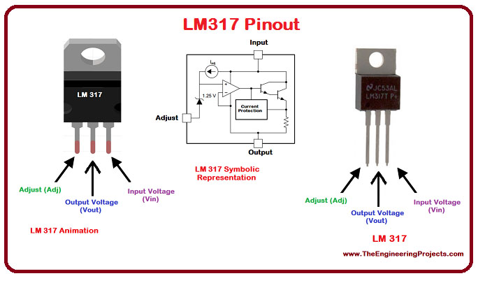
LM 317 pins configurations along with the properly labeled diagram is shown in the figure below. The animated LM317, its symbolic representation and the image of the real LM317 all are shown in the above figure.
LM317 It is a variable voltage regulator i.e. supports different output voltage levels for a constant applied input voltage supply. If you want, you could connect a fixed value or variable resistor at its Adjustment (Adj) terminal in order to control the level of the output voltage according to the requirements of the circuit. In other words we can say that LM 317 can step down the voltage from 12V to several different lower levels.
Use the below calculator and select values for R1 and the voltge that you want, and then click calculate. That will give you the value you must use for R2. For example, set R1 to 240 ohms and set an output voltage of 24V. That will give you a value for R2 of 4368 ohms.
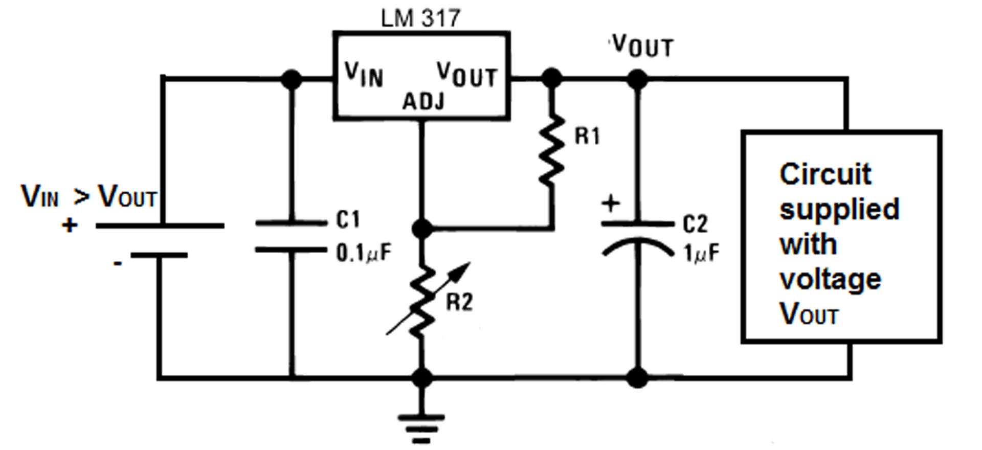
LM317 is an adjustable voltage regulator which takes an input voltage of 3 - 40V DC and provides a fixed output voltage of 1.25V to 37V DC. It requires two external resistors to adjust the output voltage. The output voltage Vout is dependent on external resistor values R1 and R2, according to the following equation:
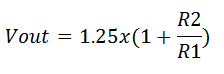
The recommended value for R1 is 240Ω but it can also be some other value between 100Ω to 1000Ω. So you need to enter a value of R2 in the LM317 voltage calculator to calculate the output voltage. For example let’s take the R2 value of 1000Ω, so according to the formulae above the calculations for output voltage would be as follows:
Vout = 1.25x(1 + 1000/240) = 6.458V
Similarly if you have a target output voltage then you can calculate the R2 value using the LM317 formulae given above. For example if the target output voltage is 10V then the R2 value is calculated as following:
10 = 1.25x(1 + R2/240) => R2 = 1680Ω
So this is how we calculate the R2 and output voltage for LM317 voltage regulator circuit. This LM317 calculator can be also be used for some other ICs like LM338 or LM350.