With this PCB I want to make my own OPTICAL POWER meter for lasers. You see, a laser power meter is very expensive so having a homemade one would be great. This project involves thermal dissipation, peltier cells, a candle, Arduino, ADCs and a lot more! You will learn a lot, the same as I did by making this experiment. Once I have all the data, I will finish the controller PCB as well. Check all the info on this post.
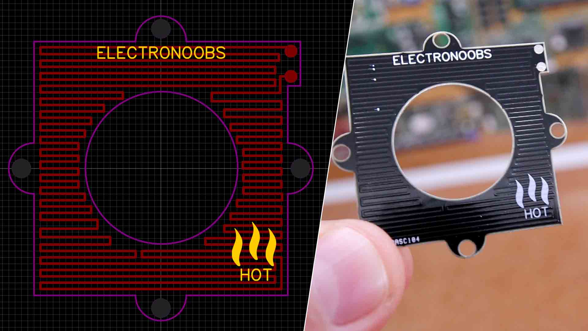
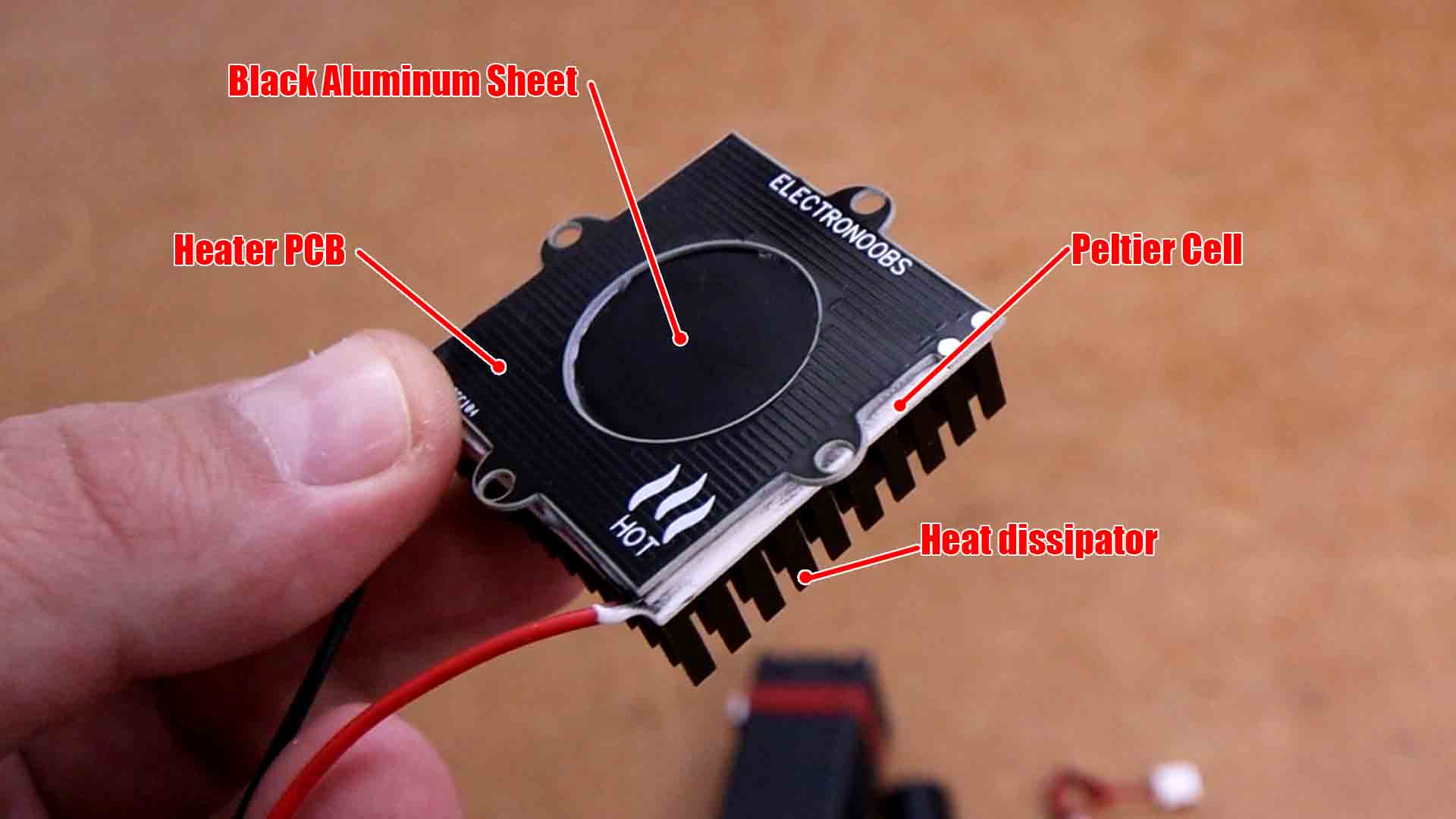
As you can see in the video, we use a Peltier cell to measure the heat difference between the cold and hot side. To compare the power of the laser, we need a heating resistor that will apply the same power, but a power that we could now measure (electrical). Fot that heating process we use my PCB desing. You must order it with Aluminum board instead of normal FR boards. Aluminum will transfer the heat a lot better.
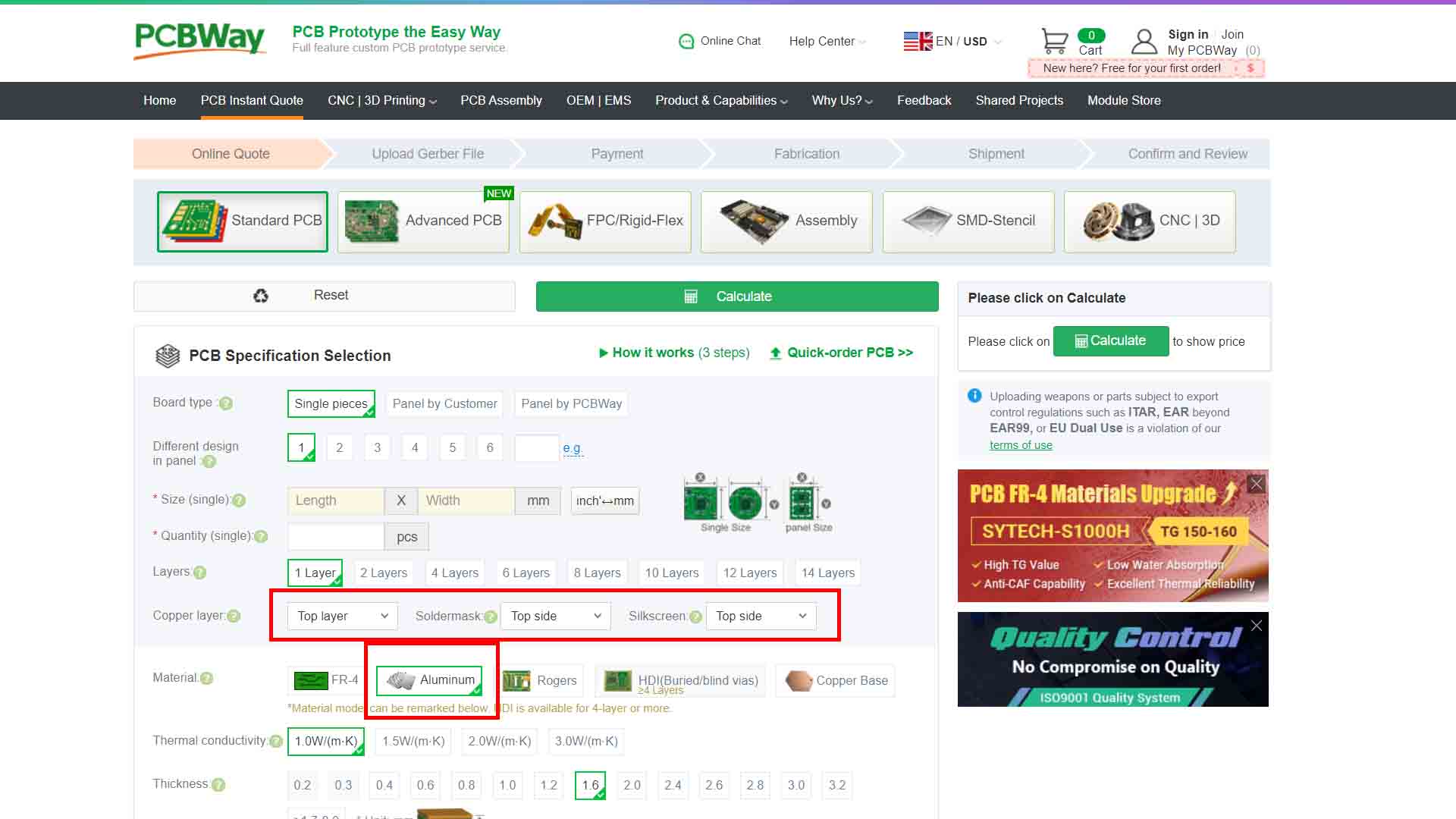
Once you downloaded my GERBER files, go to PCBWay.com and order the boards. Make sure that for material, instead of the comon FR-4, this time you select Aluminum and for the copper layer select all as "top side". For the controller PCB you can just order it as usual.
Making the block is easy. First, use thermal paste or thermal glue, and glue a sheet of black coated aluminum on one side of the plltier cell. On the other side, glue the heatsink. On top of the black aluminum sheet, glue the heater PCB using thermal paste/glue. Now measure the voltage out of the peltier cell.
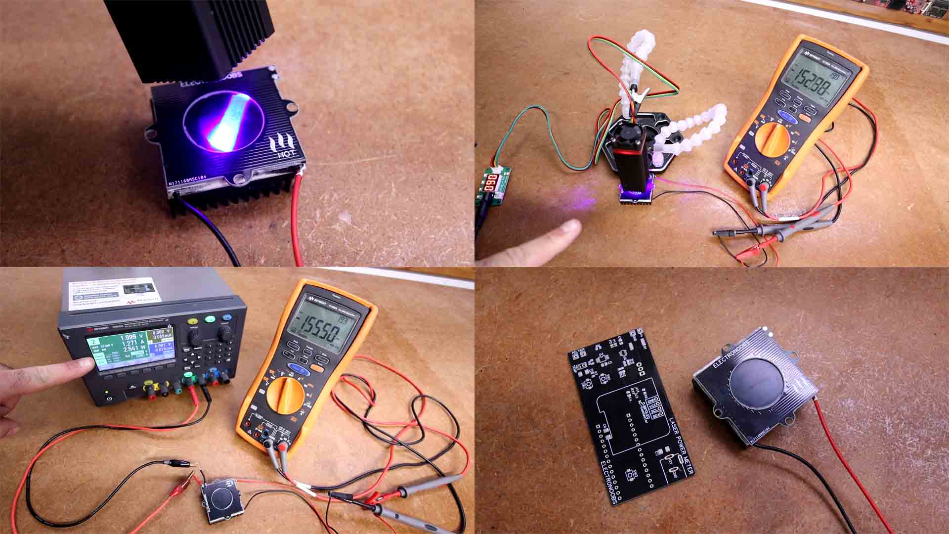
The experiment is easy. Make sure you remove the focus lens from the laser. Make sure the light fills the black metal sheet and while is heating up, measure the voltage output of the Peltier cell. Wait till the volage doesen't increase anymore, that's the balance point. Write down the value. Second step is to apply voltage to the heater PCB and start increasing the power till you reach the same balance point volage on the multimeter. At that point, write down the power it appears on the power supply and that's it. That should be the power of the laser (not taking in consideration light reflection adn heat transfer losses...)
If my videos help you, consider supporting my work on my PATREON or a donation on my PayPal. Thanks again and see you later guys.