FOC stands for FREE OF CHARGE so leave a comment below, doesn't cost you anything HAHAHAHA. Once you do that, let's get serious and tell you that FOC actually stands for Field Oriented Control. I’ve made such a driver in a previous video but a bunch of you told me “that's not actual FOC control, where is the feedback”. Anyway. That was FOC control but the encoder I was using got burned, remember? So I could only test the open loop circuit. Now I have a new PCB and this time I’ve made it with two sensors, a cheap one and an expensive one. Surprise surprise, the cheap one actually works better. This is my journey of creating hub motors like those Boston dynamic dog robots are using. For that I need torque, speed but also precise control. Brushless motors have the torque and speed, but stepper motors have the precise control. But you could actually take a brushless motor and instead of controlling it very fast, we can spin it slowly but very precisely using FOC. So if you want to make your own robot dog, you need to see this and learn a lot about FOC. Let me show you everything about this PCB, the code, the circuit and how we can control the motor, this time with a closed loop. So, let’s get started.
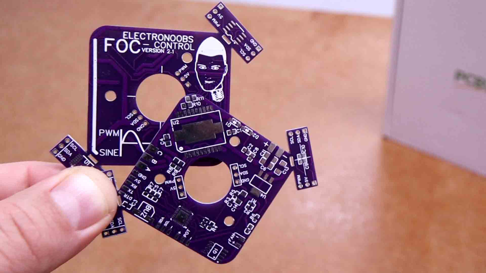
Obviouslly you need my PCBs so download the GERBERs and orther them at PCBWAYT.com. To get the sensor smaller PCBs just snap them with your hand and like that you will have 3 PCBs at the price of just 1. On the main PCB we have the ATmega328 chip for the main microcontroller, and the L6234PD for the motor driver. The PCB has extra stuff such as a buzzer for sound notifications, a MOSFET and a fan output to cool down the components and two inputs for a potentiometer or i2c control. Check the full list below.
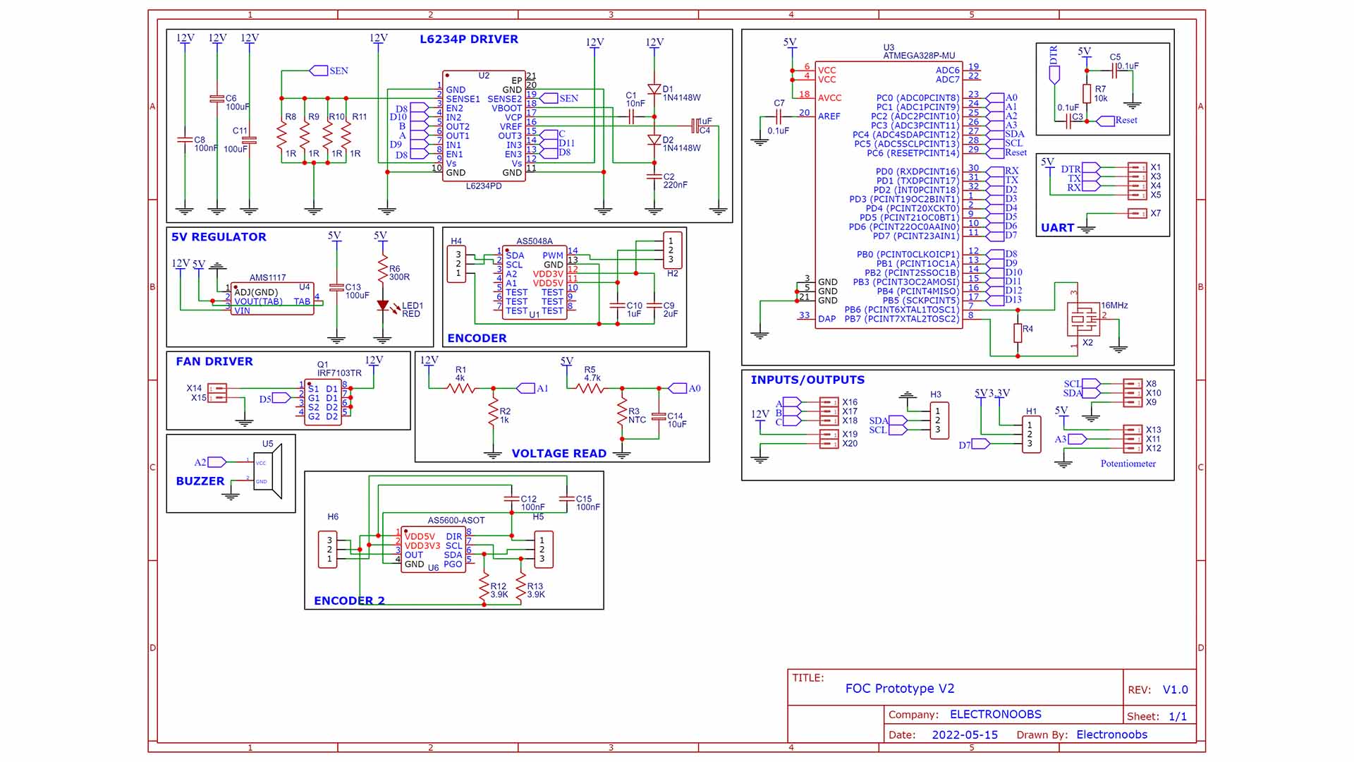
On the main PCB we have the ATmega328 chip for the main microcontroller, and the L 62 34 PD for the motor driver. The PCB has extra stuff such as a buzzer for sound notifications, a MOSFET and a fan output to cool down the components and two inputs for a potentiometer or i2c control. It has pins for the sensors (are the same for both sensors) and for the brushless motor output and 12V main input. It also has pins for i2c and a potentiometer on the side.
Now the PCB kind of looks the same as the previous one but it has some changes. I’ve ordered it in purple form PCBWAY. This time it has two sensors and I’ve made it so you could just snap the sensor PCB with your hand without having to cut it. So if you want to try this awesome project, get my GERBER files from below and then go to PCBWay.com. Here it is very easy to order for just 5 dollars. Click the quote now button. On the next page add the size of the PCB, the amount and select a color. This time I’ve selected the purple one. Add to cart and on the next page upload my GERBER files and place the order. That’s how easy is to use the services of PCBWay for PCB prototyping. As always I receive the PCBs in a few days and they look awesome. I think that for this project I like better the purple color than the red one from the previous version.
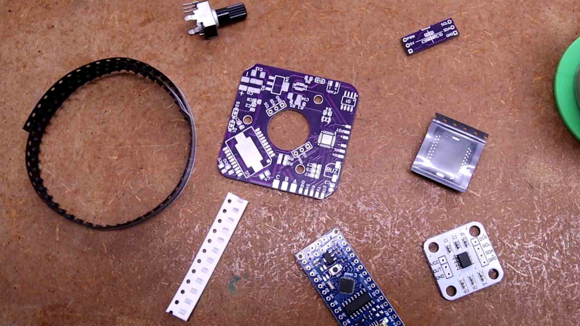
That being said, let’s assemble the PCB. I’ve taken the main microcontroller out of an Arduino NANO clone in order to know for sure it has the bootloader. You see, I’ve also bought some ATMega328 chips. But those are blank chips without a bootloader. We could burn a bootloader but we need access to the ISP pins, which this PCB doesn’t have. I place the ISP pads on pretty much all my PCBs, as you can see on these boards, we have the MOSI and MISO pins. But now, when I need them most, I forget to add them. I’m such a genius.
Anyway, the first thing I’ve soldered was the ATMega chip, the resonator, the reset pullup and the DTR capacitor. The values are on the schematic. Then I test it with one of those FTDI programmers. Upload any code to it and if it works, then the chip part is good to go.
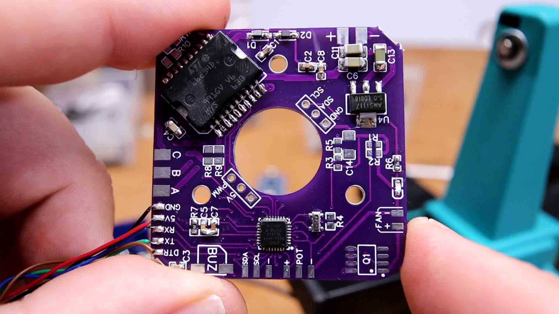
Now that the chip works, I solder the rest. Starting with the driver chip. This could handle up to 4 amps and it will get quite hot, trust me. That’s why the PCB has pads for a cooling fan but we won’t need it for tests.
Solder the small resistors and capacitors, some diodes, an LED and that’s it. Then on the small PCB I desolder the magnetic encoder from a module and solder it to my PCB. Then Add the encoder PCB on top of the main PCB. The motor gets soldered to the 3 pads for phase A, B and C. And the board will get on the back of the motor using screws, face to face with the magnet that we have glued before to the shaft using some super glue. Now the setup is ready for the code.
The PCB has UART pads for an FTDI programmer so connect it and then add the USB cable and let’s start with some tests.
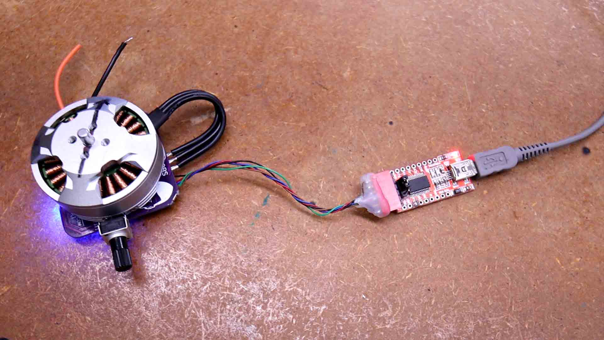
I have two boards, one with the AS 5600 sensor and the other with the AS5048. Even if the AS5048 is a lot more expensive, for some reason I only was able to make it work in PWM mode and PWM mode is not as precise as i2c. That’s why I’ve decided to continue with the 5600. So first test is to download the amd 56 00 library and run the read angle code. Upload the code and open the monitor. As you can see, I can now see the angle when rotating the motor so the sensor is working.
//Inputs or outputs
const int potentiometer = A3;     // pot controls the RPM speed
const int MotorPinPhase_A =9;     //Driver's pin for coil A
const int MotorPinPhase_B =10;    //Driver's pin for coil B
const int MotorPinPhase_C =11;    //Driver's pin for coil C
const int buzzer = A2;            //Pin for the on board buzzer
const int fanPin = 5;             //Pin for fan MOSFET
const int supplyVoltagePin = A1;  //Pin for reading the supply voltage
const int temperaturePin = A0;    //Pin for reading the temperature with the NTC
const int PWMSensor = 2;          //PWM output from the magnetic encoder sensor (not used in this code...)
It has quite some torque and I’m running it at 7V because at more power, the driver gets quite hot.
You can rotate it a lot and it will still get back to the original position. That’s quite awesome to see.
By the way, this is also compatible with the simpleFOC library so you could download it from GitHub and test it out, it has some nice features.
For example, my motor could only go from 0 to 360 degrees but for now the code is not made to make more than 1 rotation. When I get to 0 or 360, the motor starts spinning as you can see here, since the error is always greater or smaller than 0. I’ll improve my code for future updates.
Now you could use my setup for your own FOC project for making a robot, a balance or any other PID controlled system with brushless motors. You’ve also learned how the poles of the motor affect the code and the feedback is implemented with the magnetic sensor. You have all my files below, the code, the schematic, the PCB files and everything you need on electronoobs.com so just download them and create your own project. I’m quite satisfied with the results. Thanks again and see you later guys.