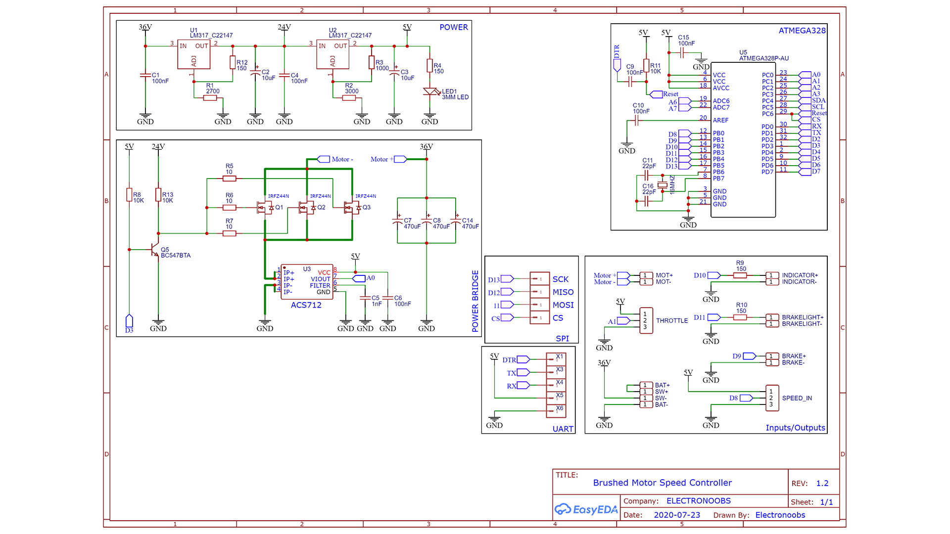
You have the scheamtic below. Remember that instead of the BC547 BJT you could add a MSOFET driver supplied at 24V and connected to the MOSFETs gate. The BJT has a pullup so it will be activated when the PCB starts, so the MOSFET gates are connected to GND, so those will be OFF. We don't want the MSOFETs to be ON for a short moment till the Arduino starts-up. The first part you will want to mount on the PCB is the "POWER" with the LM317 regulators. In this way, if the supplies fails and the output is higher than 5V, we won't burn the other components... Then add the ATmega328 basic configuration and then the rest of components.
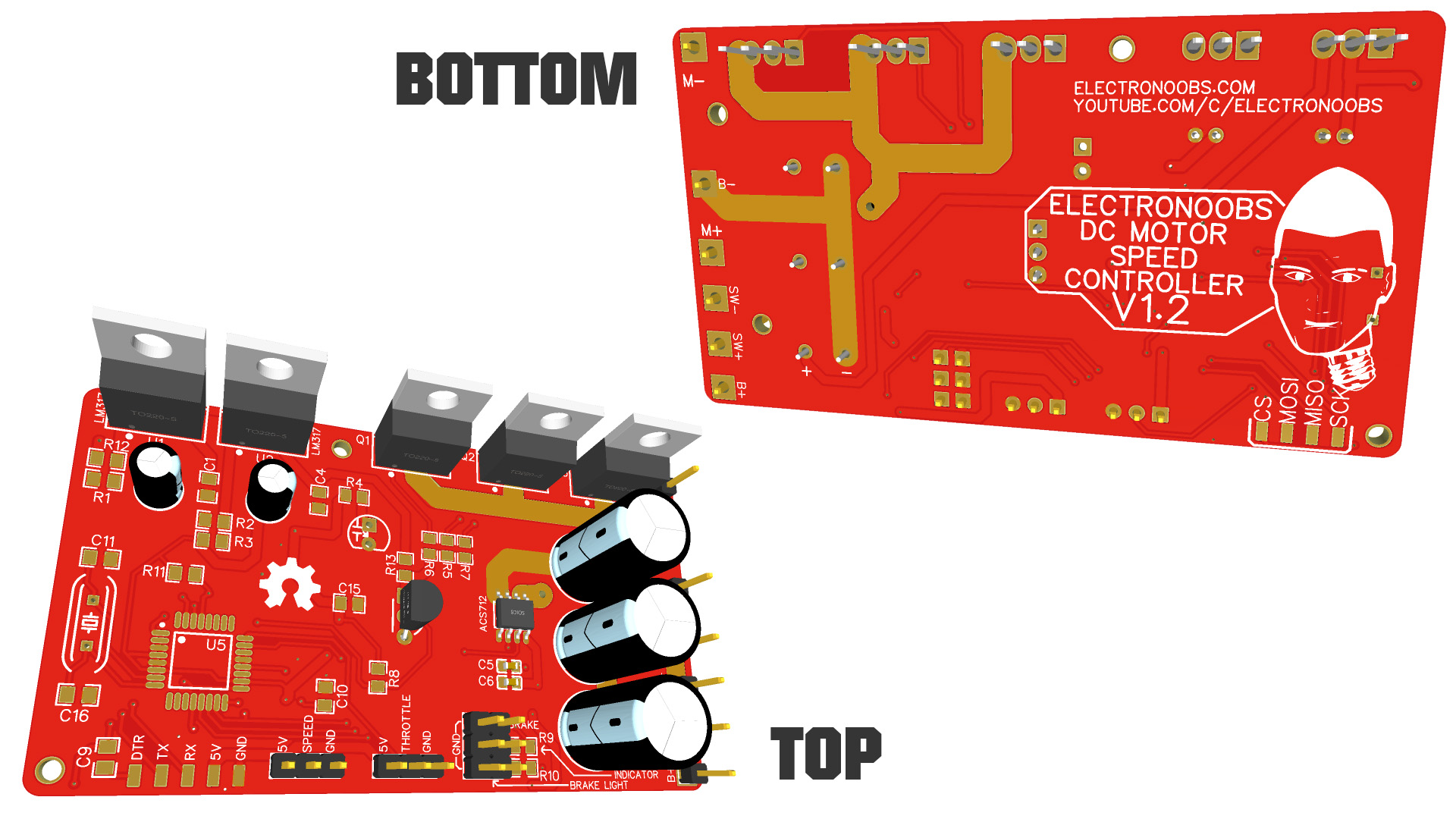
You can make your own circuit on a breadboard for tests or maybe on a drilled prototyping PCB but if you want my PCB, you can download it from belwo for free. So go below, downlaod the .zip file with all the GERBERs and send it to a PCB manufacturer and get the boards. Then together with the schematic abobe and the part list, mount this project. Then upload the code and test it...
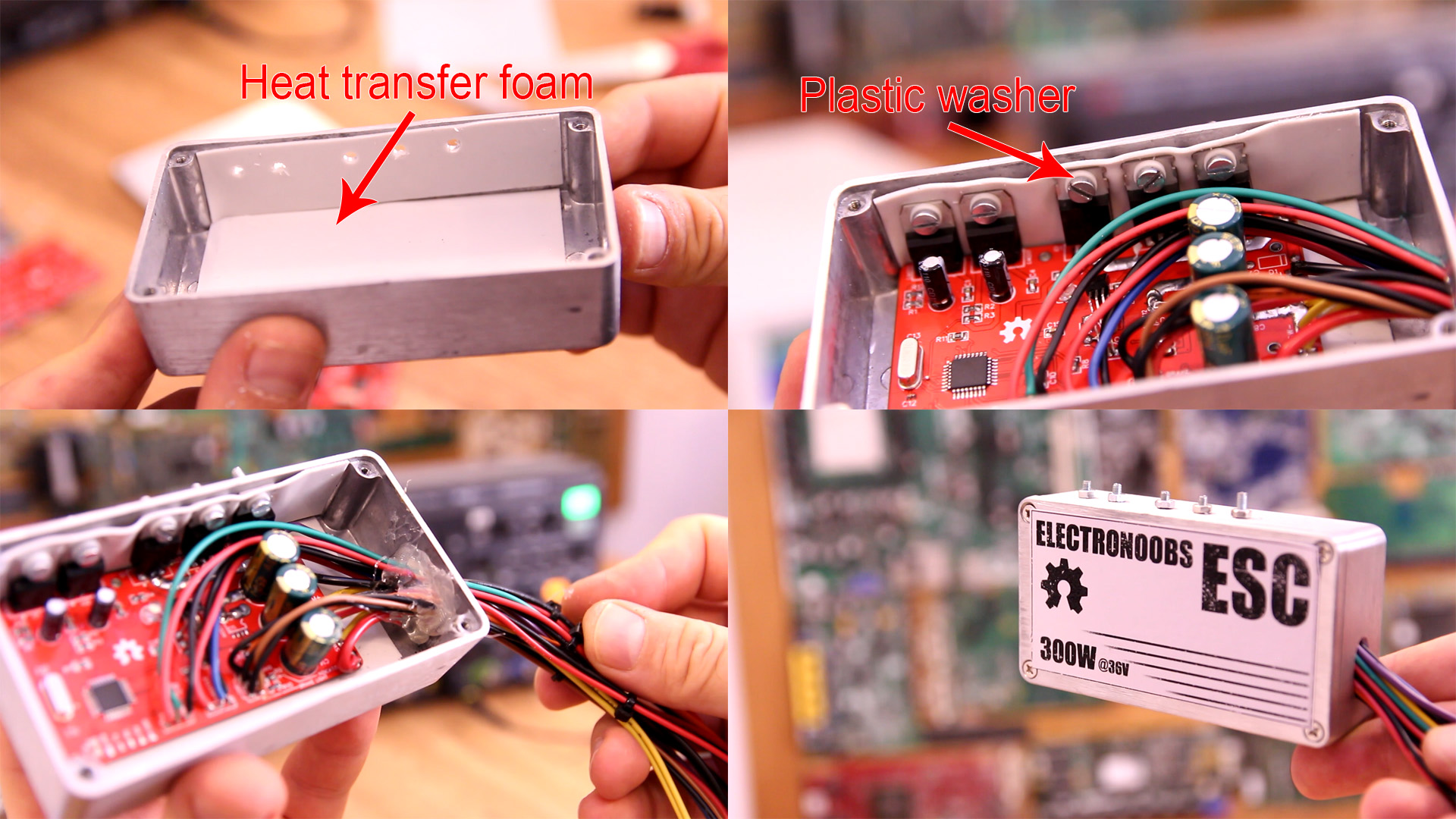
The case is as important as the PCB. Without a good heat dissipation, the MOSFETs would burn out in seconds. So, I will use this small metal case below. Measure and make the holes. Then I add some heat transfer paste between the MOSFETs and case but also below the PCB so it won't touch the case and create a short circuit. Once insulated, add the screws. Use a plastic washer for the screws so they won't touch the metal part and create short circuit. Add all wires, make a hole, pass the wires and glue them in place. Close the case and add label. That's it.