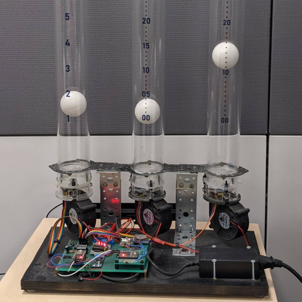
If you’ve ever had surgery, and you’re over a certain age, chances are good you’re familiar with the dreaded incentive spirometer. It’s a little plastic device with one or more columns, each of which has a plastic ball in it. The idea is to blow into the thing to float the balls, to endure that your lungs stay in good shape and reduce the chance of pneumonia. This unique air-powered clock reminds us a little of that device, without all the pain.

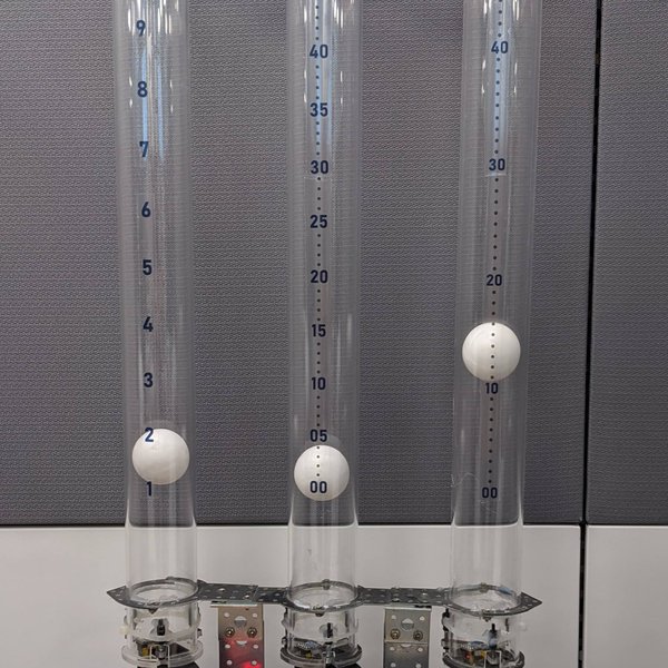
Like a spirometer, [Nir Tasher]’s clock has three calibrated tubes, each big enough to hold a foam ball loosely. At the bottom of each tube is a blower whose motor is under PWM control. A laser rangefinder sits below each ball and measures its height; the measurement is used by a PID loop to control the speed of each fan and thus the height of each ball. The video below shows that the balls are actually pretty steady, making the clock easy to read. It doesn’t, however, reveal what the clock sounds like; we’re going to go out on a limb here and guess that it’s pretty noisy. Still, we think it’s a fantastic way to keep time, and unique in the extreme.
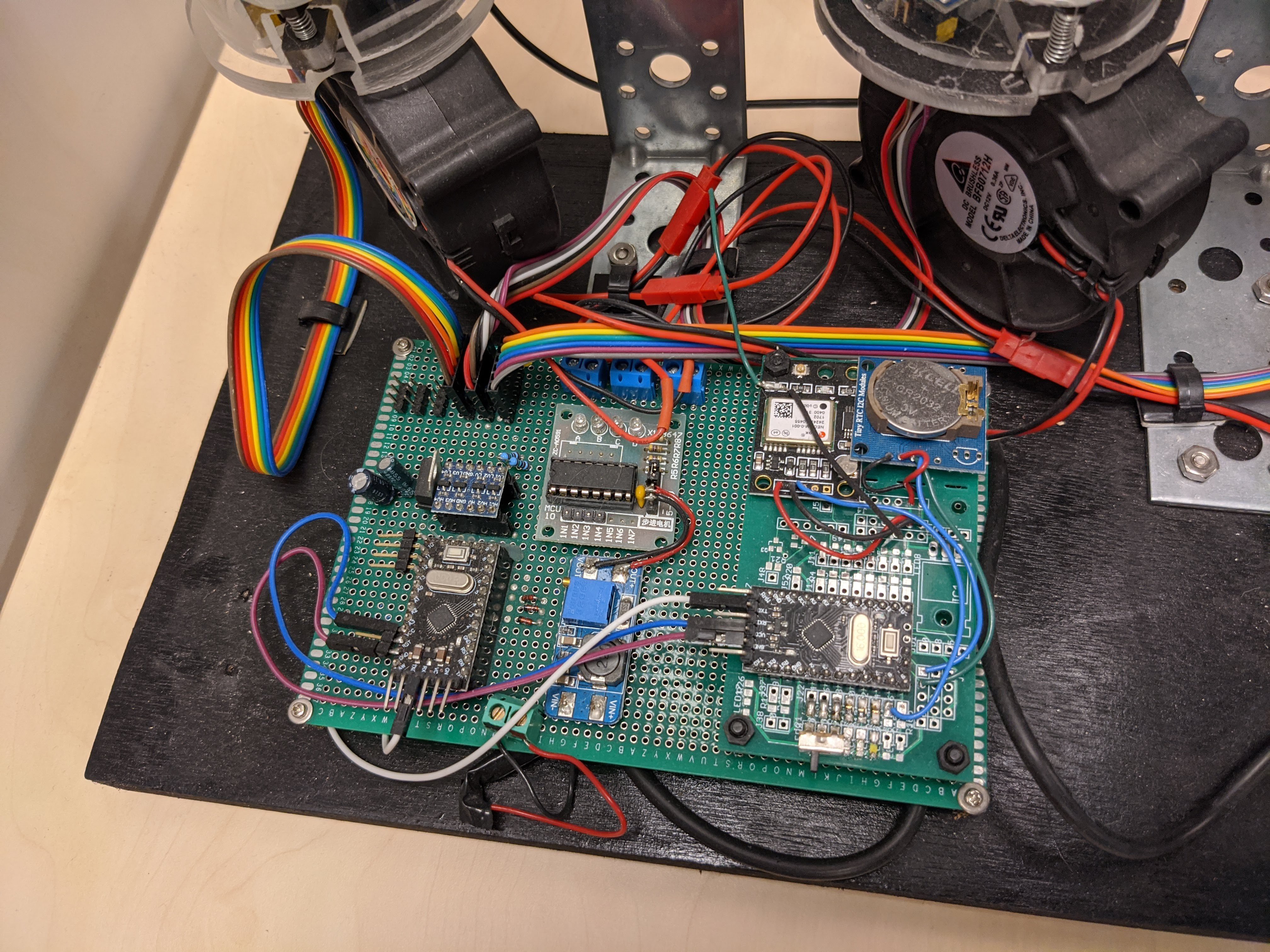
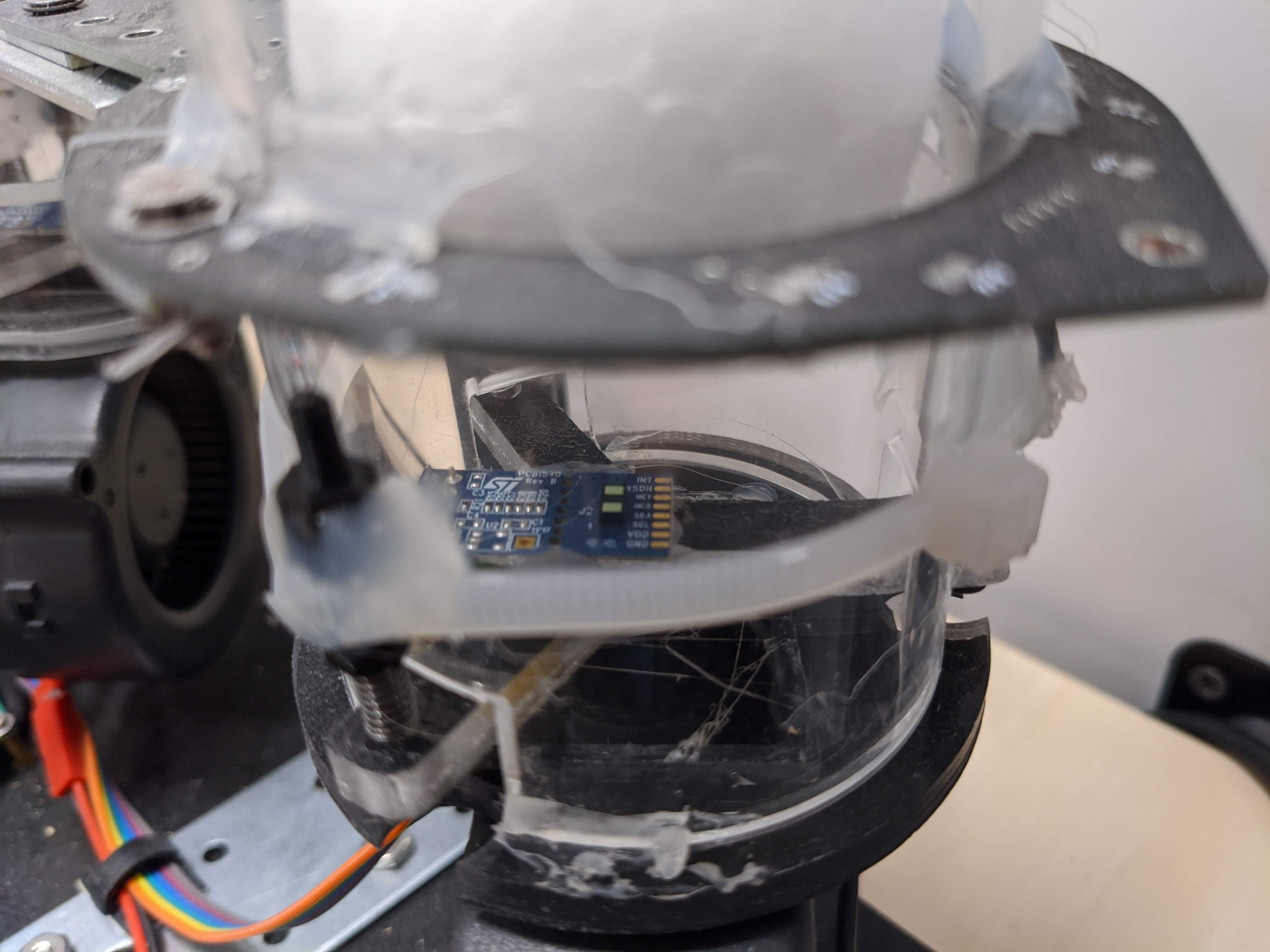
The VL53L1X sensors were used since the detection angle can be controlled by the user down to 4 degrees which is what I needed to measure the distance of the foam balls within the transparent pipes. A wider angle would have caused reflections from the tube walls to interfere with the longer readings.
PID control is simple but when the seconds/minutes/hours wrap from max to min, the loop parameters must be changed to make sure the ball stops before hitting the bottom - so a strong differential gain is needed. In normal operating strong differential gain would drive the balls into oscillation.
All the small plastic parts were cut with a cheap desktop CNC machine. Each laser sensor is held at 3 points so it
All of the modules are off-the-shelf in order to keep cost down and minimize the building and soldering work. The only exception are the parts used to hold the tubes together. My initial idea was to cut them from plexi-glass the same way I did with the laser sensor holder and fan adapter but it didn't pan out as I wanted. I then decided to order the parts from a contractor and searched on-line for one but the price was too high. Finally I came up with the cheapest and most robust idea - make these parts from FR-4 PCB material by designing a PCB and sending it to be produced as prototype. This proved to be the cheapest and most rigid solution. I even made provisions to install LEDs on these PCBs but didn't get to it.