What’s up my friends, welcome back. Let’s see how to make a good homemade laser power meter. For today I’ve made this PCB and is made to be quite modular. As you can see it has all sorts of inputs and outputs and that's because I’m still testing the best option to measure the light power of a laser. So if you want to make the same project and save almost 200 dollars, download for free my GERBER files from below.
Get the PCB and on it we have a space for a USB type C charger. To make precise measurements, I’ve added a 16 bits ADC module. On the front we have the pins for an OLED display so we could see the measurements. It also has two push buttons. Then, we have a space for a buzzer for sound notifications. We have space for an NTC on board so we could measure the ambient temperature. But then we have two pins for yet another NTC that would go on a heat dissipator. Then we have the input from a Peltier cell and also the output for a fan like this one but I might not use it for today. Last pins are for the battery and the on and off switch which in my case I will use one like this one and a small 3.7V lipo battery. And by the way, I’ve took some time and designed an enclosure as well so we need to 3D print it and the files are below as always.

The schemartic is simple. All the modules connected to the Arduino with i2c communication or direct connection. Check the schematic for any value.

First of all, my new design of the PCB. If you want to make this awesome project and challenge yourself you can download my GERBERs for the PCB from below. As always I’ve used the services of PCBWAY to create these awesome boards. Once you have my files, go to PCBWAY.com and click the quote now button. Here select your settings. I leave all by default and I set the color to black so it would reflect less light inside the case. On the next page upload the GERBERs and make the payment and in just a few days I received my PCBs. This design turned out awesome!
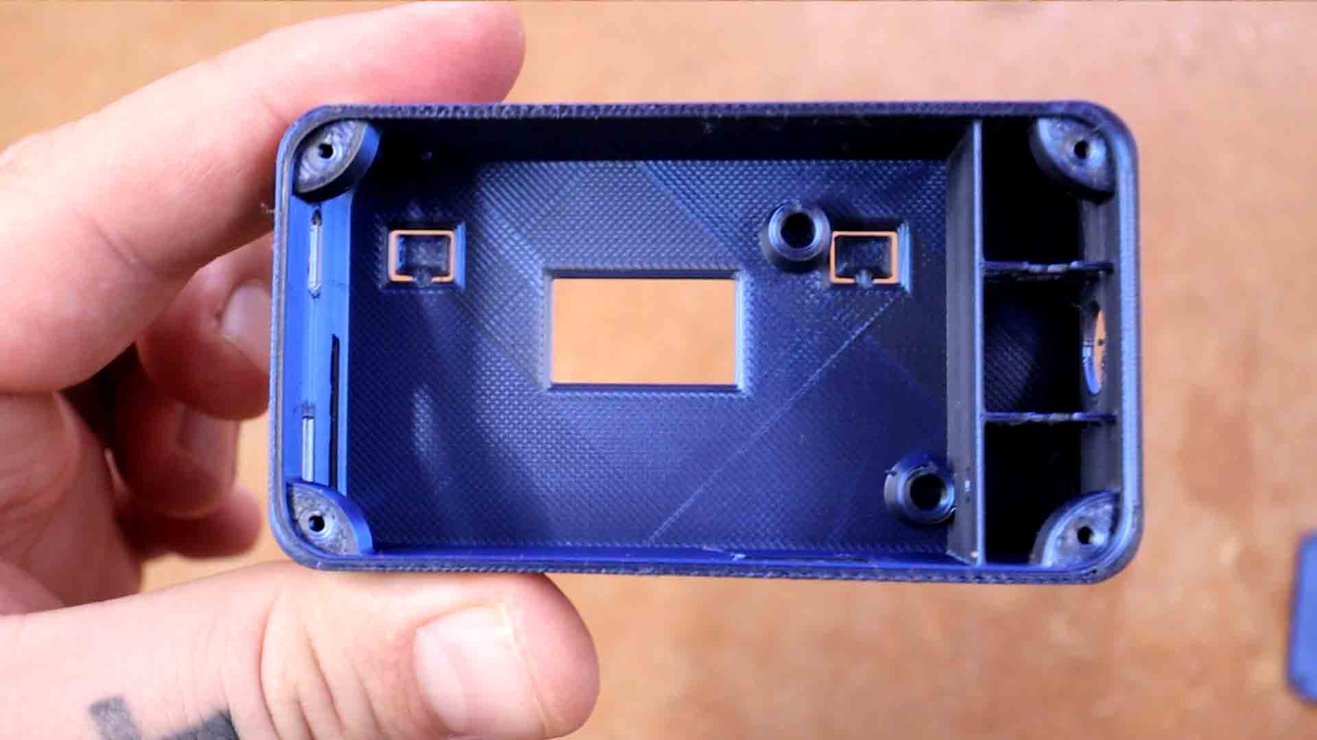
Download my 3D files from below. We have only 2 parts: the main case and the lid. The case already has this slots for the push buttons so we don’t need separated printed parts for that. Get two insertion nuts like this one and using your soldering iron, stick them in place.
Take the PCB and place it inside the case and add two M3 screws. You should be able to see the USB charging connector and the USB of the Arduino on the side of the case. Add the on and off switch on the top side. Solder wires from the switch to the PCB. On the battery pins I add a 4V LiPo battery. Add the cell with the dissipator inside this space here with the cell facing outward of the case. Pass the wires and solder them to the PCB on the Peltier pins and the meter should be ready for calibration.

Upload a simple code to the Arduino. That will print the analog read from the Peltier cell on the OLED screen. So this is what I will do: Using the commercial meter and a laser, I measure the power in steps of 10% so 10, 20%, 30 and so on. Then I do the same but with my homemade version and write down the analog read. So in that way I get the real measured power, the power percentage and the measured analog read and with this values, in Excel I make a graph like this one. I get the transfer function and apply that in my Arduino code and now instead of analog read, I can print power. My code will have in the future some other calibration steps including room temperature, but for the first firmware, this is enough for testing.
Now we can measure. First with the commercial meter. Then with my homemade version. The results are the same. I don’t know the precision and we will address that topic on my next video so make sure you are subscribed. The main problem will be the room temperature. If you’ve watched my experiment video, you know this setup is based on heat absorption on the black painted side and dissipation on the heat dissipator. So if you measure a laser in winter and at 10 degrees room temperature, the result might be different in the summer, at 30 degrees room temperature. And I say might because I can’t know for sure.
That’s why I have these 2 buttons, the fan control and two extra NTC for temperature measurement and calibration so stay tuned for the second version of the firmware with a lot more precision and accuracy. Anyway, my homemade version is almost 20 times cheaper than the AliExpress version so I think the project was a success.