
 About me
  History
  Let's learn
  Contact us
  Arduino tutorials
 Circuits tutorials
  Robotics tutorials
 Q&A
Q&A Blog
Blog  Arduino
  Circuits
 Robotics
  Modules
  Gadgets
  Printers
  Materials
  3D objects
  3D edit
  Donate
  Reviews
  Advertising


Homemade electric scooter
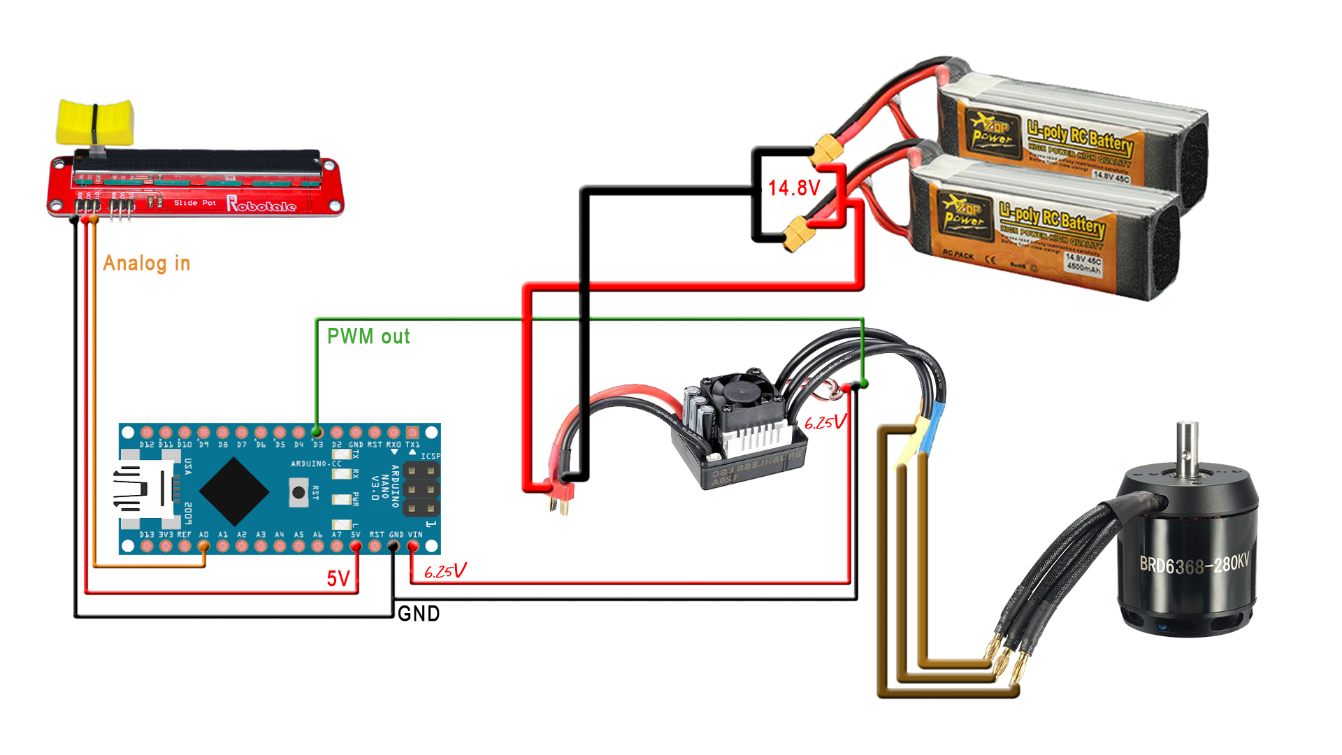
In this part we will mount the electronics part. We have to solder wires to the potentiometer. Those wires are 5V and GND from the arduino. The middle pin will be the analog read. Next, inside of the arduino code we create the PWM signal and apply that to the ESC. The ESC will control the power to the brushless motor. With the 14.8V LiPo battery we supply everything.
4. Electronics
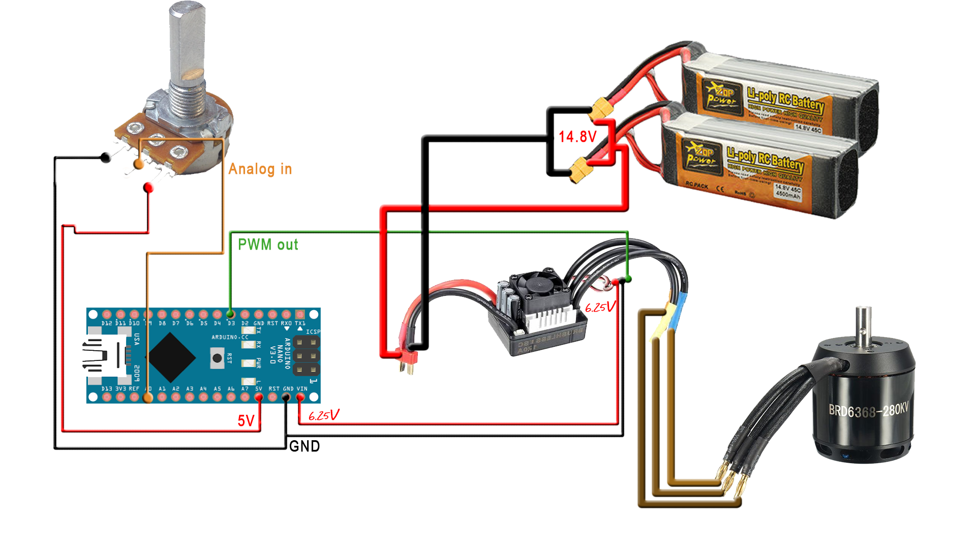
First take a look at the scheamtics below. There are two dependingo on the potentiometer that you use. Make sure you check everything before start soldering and mounting the components. The schematic is easy, just connect the batteries in paralel to have more capacity. Then connect the battery pack to the ESC and power it. The ESC has a 6.25V BEC output that will supply the Arduino part of the schematic. Connect that 6.25V to the Vin pin of the Arduino. Finally connect the potentiometer to the analog A0 pin of the Arduino and alos share 5V and GND with it.
We have to test everything if it works. For that connect everything on a test board or so and upload the enxt code. This code will read the value on the potentiometer and apply a PWM pulse to the ESC.
Electric scooter code:
4.1 Bild the case
Download the bottom and top 3D parts for the case, link is below. Print them following the instructions there. Also cut the 4 plywood pices for the sides. Prepare the plywood sheets and add carbon fiber vinyl for better look. Now place the batteries on the bottom support as we can see below.
Main case STL files:

Now that we have the battery in place and the plywood sides places, we prepare the front part of the case. We have to place there the ESC. Thw annoing thing is that the ESC will only start if the small push button is pressed so we have to add a hole and a 3D printed button so we could start the ESC from the outside of the case.
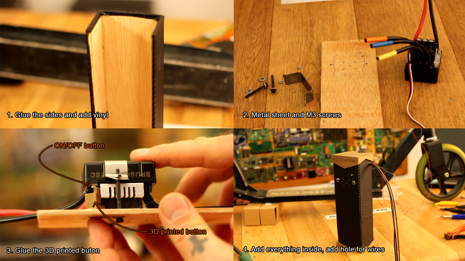
We fix in place the ESC using M3 screws and a thin metal sheet. Be careful that the plastic button is in front of the push button. Now solder the wires from the potentiometer to the Arduino, 5V, GND and analog pin A0. Also solder digital D3 pin to the ESC and also share GND with it. pass the 3 wires from the motor to the inside of the case and solder them to the ESC. Remember to use a lot of heat shrinking tubes for insulation.
Now we can close the case and screw it in place on the main axis of the Scooter using small M3 screws. Then pass the wires to the motor. I've used zip ties to fix those wires in place.

Now that everything is prepared, let's chech the code. In the next part we have the code esplained for the HOMEMADE electric scooter. Upload that code to the Arduino NANO. make sure that you have the correct range for the potentiometer.