In this tutorial I'll show you the circuit of a basic wireless charger, the transmitter and receiver. See how to adapt the resonance and transfer power. Then how to regulate the receiver output at 5V so we could charge a smartphone via USB. Hope you'll learn something new.
Below you have all the parts needed for this circuit, both transmitter and receiver. Select the size you need for your drilled PCB. The transmitter capacitors are unpolarized and Polypropylene. For the receiver we use polarized caps Elecrtolytic. I've made my coils on top of a round bottle and used super glue to keep the wires in place.
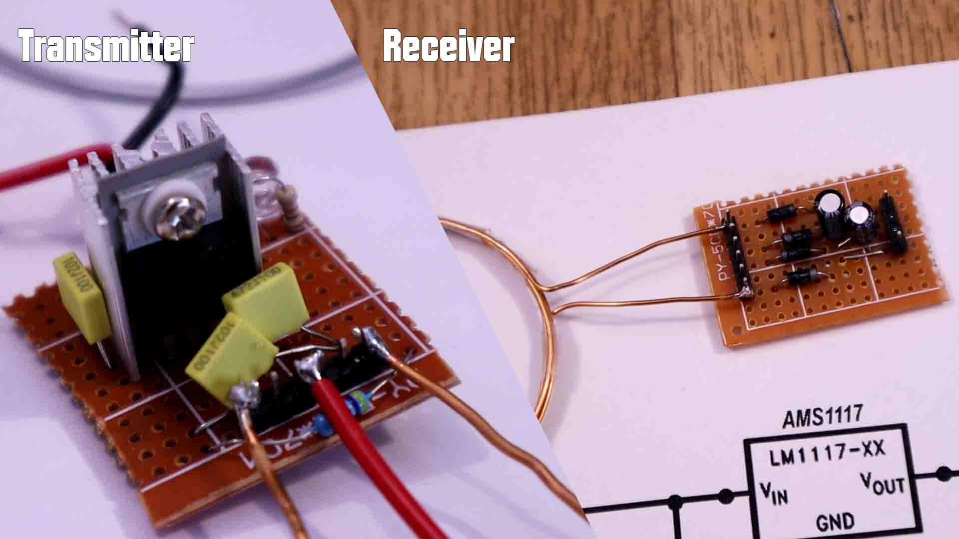
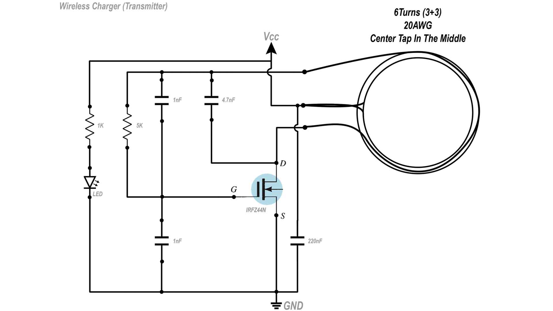
This is the circuit for the power transmitter. Depending on how you make the coil, it will affect the resonance frequency together with the 220nF capacitor that creates the LC tank. The diameter and amount of loops of the coil is important. In my case, for my tests the diameter was 8cm and I've used 6 loops with center tap in the middle, so 3 loops before the middle point and 3 more after. This circuit will automatically create the resonance frequency and even we change the load, the circuit will automatically adapt. Since the gate of the MOSFET is connected to the coil. each time the voltage oscilaltes, it will turn the transistor on and off and like that creating the oscillations. The LED is just for indication that the circuit is powered on.
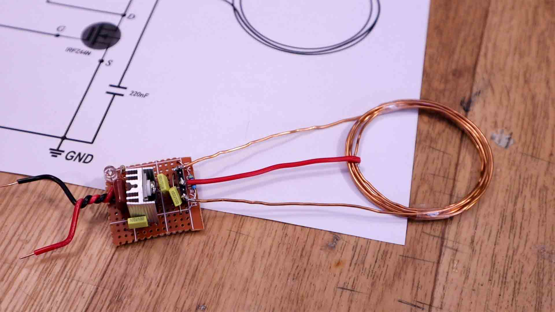
I've connected everything on a piece of drilled prototyping PCB. Using two thick wires as input and then making the connections to the MOSFET. To solder the coil, I've used some male pins on the PCB. To make the coil I've soldered togeter two equal copper wires and then I've made 3 loops on one side and 3 more on the other. In this way we have the center tape equal on bot sides.
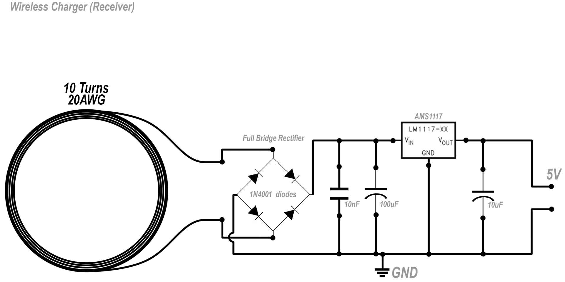
This is the circuit for the receiver. I've made the coil with 10 turns so it will output a bit higher voltage. Then, first step is to rectify the signal with the diodes bridge. We filter the spikes with those capacitors and then we regulate the output at 5V using the AMS1117 regulator or any other. We add a filter cap at the output and that's it for the receiver. Even the voltage from the receiver coil is 16V, the AMS1115 will keep the output always at maximum 5V.
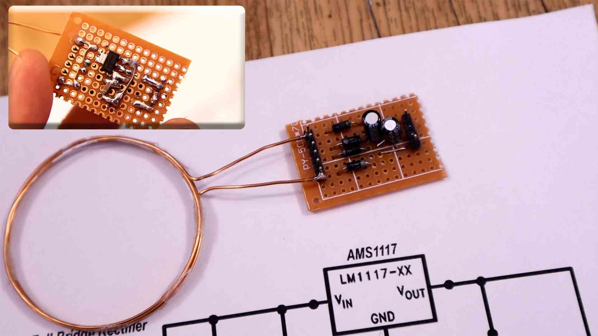
I've connected everything on a piece of drilled prototyping PCB. Once again I've used male PCB pins to connect the receiver coil which in this case is 10 turns. I've used the diodes and made the rectifier, add the capacitor and voltage regulator on the back and that's it. We could now connect a USB wire at the outout and supply my smartphone.
In the test video below you can see how the output is limited at 5V on the multimeter. Also how with a USB cable I'm able to charge my smartphone and actually transfer more power than the commercial charger I've bought from eBay. The circuit works ok but it could always be improved with more tests and changing the coil parameters and add some more components to the circuit.
Please see more in the video tutorial. I hope that you like this video and more important, that you have learned something new about wireless cahrgers, smartphone charging and voltage regulators. If so, maybe give a like the video below and consider subscribing. If my videos help you, consider supporting my work on my PATREON or a donation on my PayPal. Thanks again and see you later guys.