

A Tesla coil generates a high frequency high voltage inside of the main coil and that ionize the air at the end of the copper wire and the air will glow due to the created arcs. Depending on the tesla coil power, the arcs could ger bigger. This project is very cool to look at but not just that. It could also wirelessly transport power for some sort of devices, like for example this small neon light. Or a compact fluorescent lamp. Be careful working with high voltage, because those could hurt you.
Let’s start with the main voltage tesla coil circuit based on the gap spark. This is the circuit. As you can see below, this one is directly connected to 230V AC from the outlet. That is connected to a transformer that will increase the voltage even more up to thousands of volts and also separate the two parts of the circuit.

That will charge up the C1 capacitor, till the voltage is high enough that a voltage arc is created between these two points. When the arc is formed, a current change will be created through the primary winding of the tesla coil. That will create a magnetic flux that will then induce a voltage drop on the secondary winding of the tesla coil. Now usually, the winding ratio between the primary and secondary is very high, so the voltage at the secondary will be very, very, high.
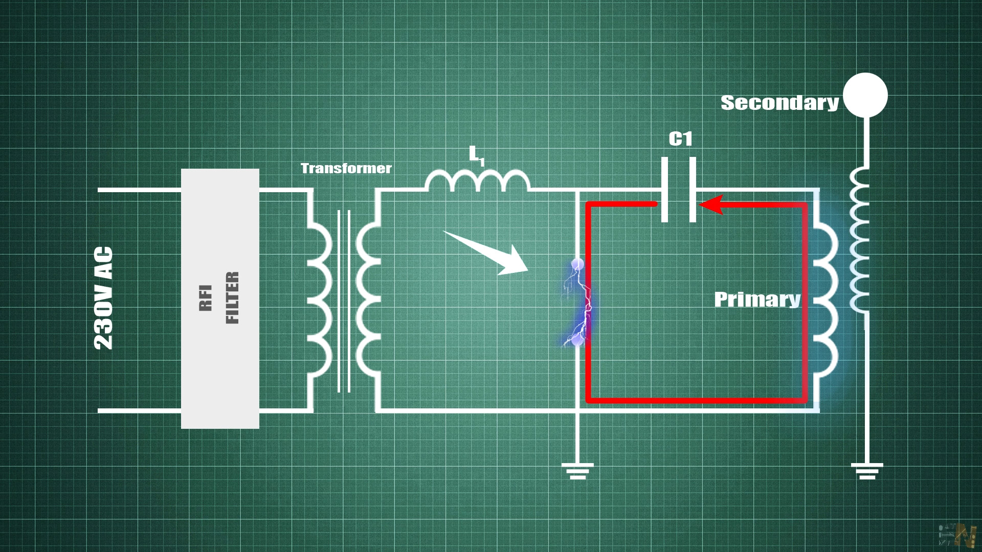
How is the voltage arc created? because this is an open loop. I mean we have high voltage on top of the coil but there is no connection to the opposite side so the spark could jump.
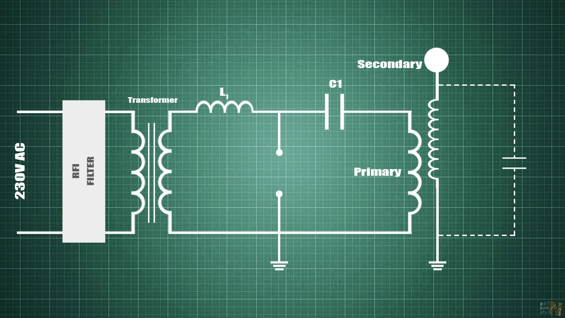
Well, actually, the voltage arc will be created between the top of the coil and a parasitic capacitance created by the air around. This capacitance is very small, but good enough. So, the air at the top of the coil will ionize and voltage arcs are created and shooting through the air.
Now, let’s take a look at the Slayer Exciter circuit and see how this one works. For this circuit we only had a BJT transistor, a resistor and a diode. When we apply power at the input, the circuit will resonate and create a high frequency, high voltage arc at the end of the copper wire. We’ve seen a similar circuit in another past tutorial when we’ve made the homemade arc lighter with a high voltage transformer from LCD screens.
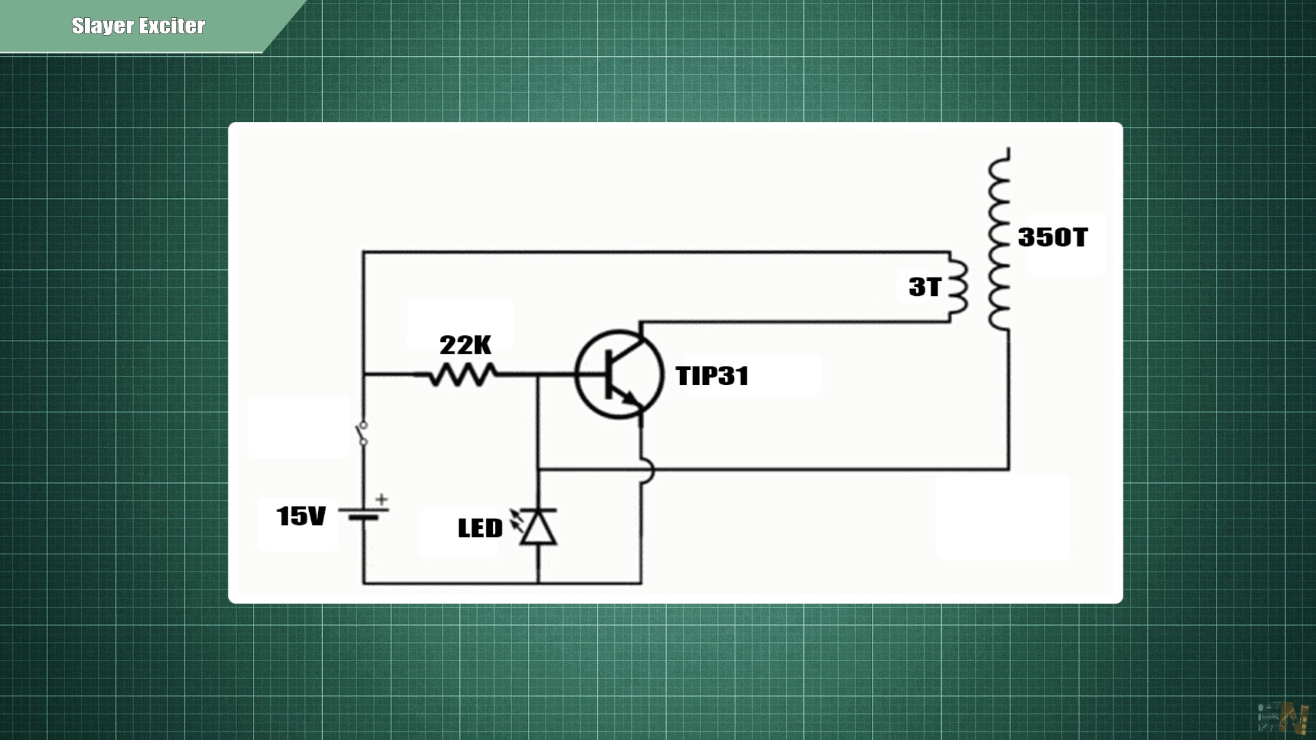
This is more than simple and works with low DC voltage. When voltage is applied to the base of this BJT transistor, the transistor is turned on and current could pas from the collector to the emitter and at the same time trough the primary winding of the tesla coil. That will induce current in the secondary and create a voltage drop. We will have the negative polarity here.
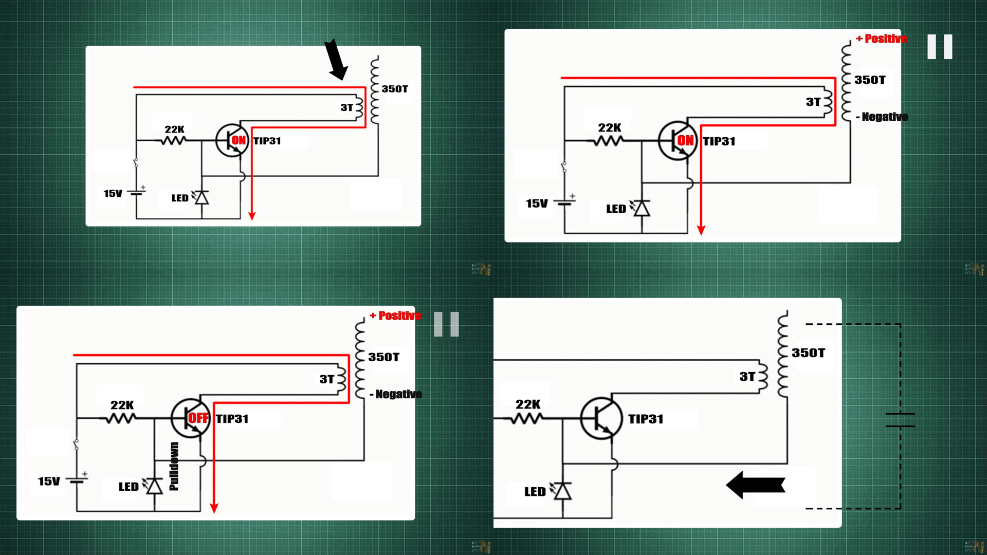
Then, in the second stage of the voltage conversion, when we cut the current from the primary, the magnetic field created will collapse and push current in the opposite way in the secondary winding. That’s why, in this configuration, our transformer acts as a coupled inductor, but if we look at the current and voltage values, the coupled inductor acts as a transformer, so we could have a gain and the inductance ratio is given by this formula where n is the amount of turns of each winding.
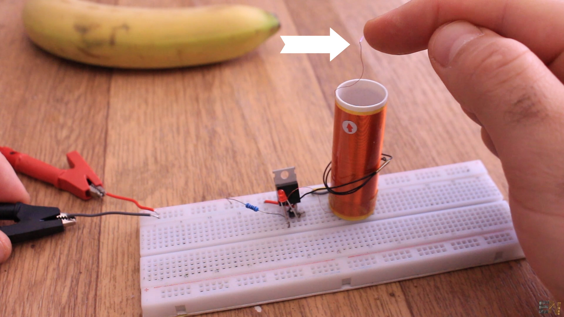
So, now this negative polarity is also connected to the base of the transistor, and when this value reaches the threshold value of the diode, it will then pulldown the transistor base and by that turn it off. But this just for a brief moment, because now the magnetic field in the primary will collapse and invert the polarity in the secondary. Now, again, the transistor is switched on and the entire process will repeat on and on and creating the resonance frequency given by the entire circuit values.
And again, if you wonder, how is the negative voltage created by the secondary, have any effect over the transistor base since there is no closed loop? Well, once again, we have that parasitic capacitance created by the air around the coil. So, now we have a close loop, and the voltage on the secondary could affect the transistor base.
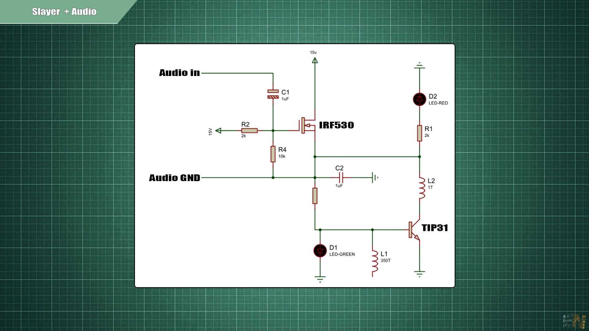
Now let’s take a look at the second circuit with audio modulation. This time we also had a MOSFET and the rest of the circuit is practically the same. I’m using the same coil made out of 350 windings of 0.12 copper wire. The coil is 55mm height and a diameter of 20mm. The primary are just two windings around the secondary and that’s it. In this case we can see a little bit more powerful arcs and when music is played, the amplitude is modulated and we can hear the music trough the sparks.
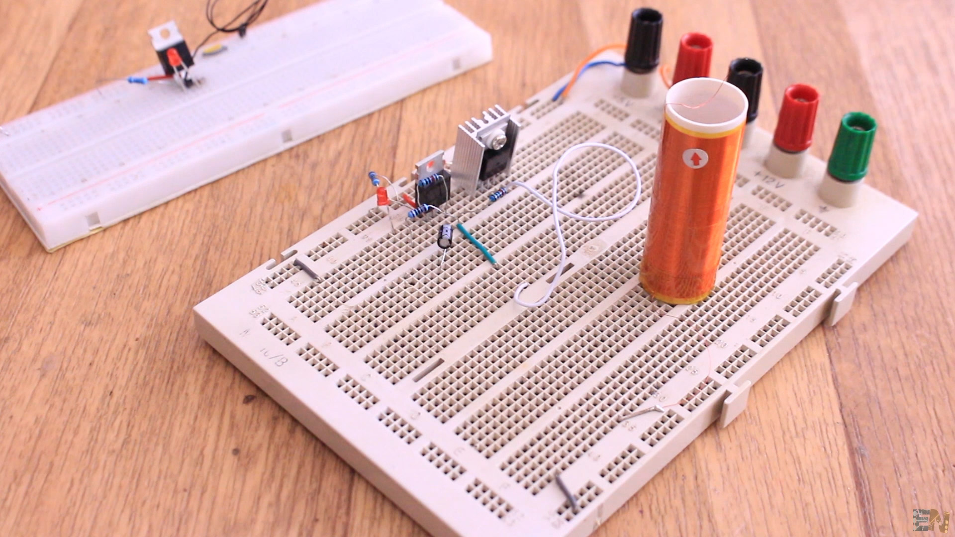
We still have the same part with the BJT connected to the primary and secondary as in the other circuit. The voltage created in the secondary, will control the BJT base and by that create that high frequency and high voltage just as before. But now music signal is connected to the MOSFET gate. That will also modulate the amplitude of the voltage applied to the primary. So, by that the final output voltage. By changing the amplitude according to the sound signal, the arcs will be stronger or weaker depending of the audio signal. So, that’s how we control this circuit with music.
There are plenty of other circuits for tesla coils that are much more powerful. I’m working myself in designing a winding robot so I could wind my own coils. Then I might make a bigger tesla coil and maybe we could learn even more about this circuits.
Now have in mind that the circuits we have seen today have no feedback control. For better and more precise circuits, we need a feedback in order to fine tune the resonance frequency and the needed voltage value for the coils. More about that in a future video.
Consider supporting my work on PATREON. Thank you!