We know that a diode will let current pas only in one direction. So, we change the second switch with a diode. In this case, when switch 1 is closed it will create a voltage of this polarity on the primary. And that will create a voltage of this polarity on the secondary. So current will want to flow opposite to the diode, so by that, the current flow will be blocked and that’s exactly what the second switch was doing when it was open. At this stage, energy will be pushed into the core of the inductor.
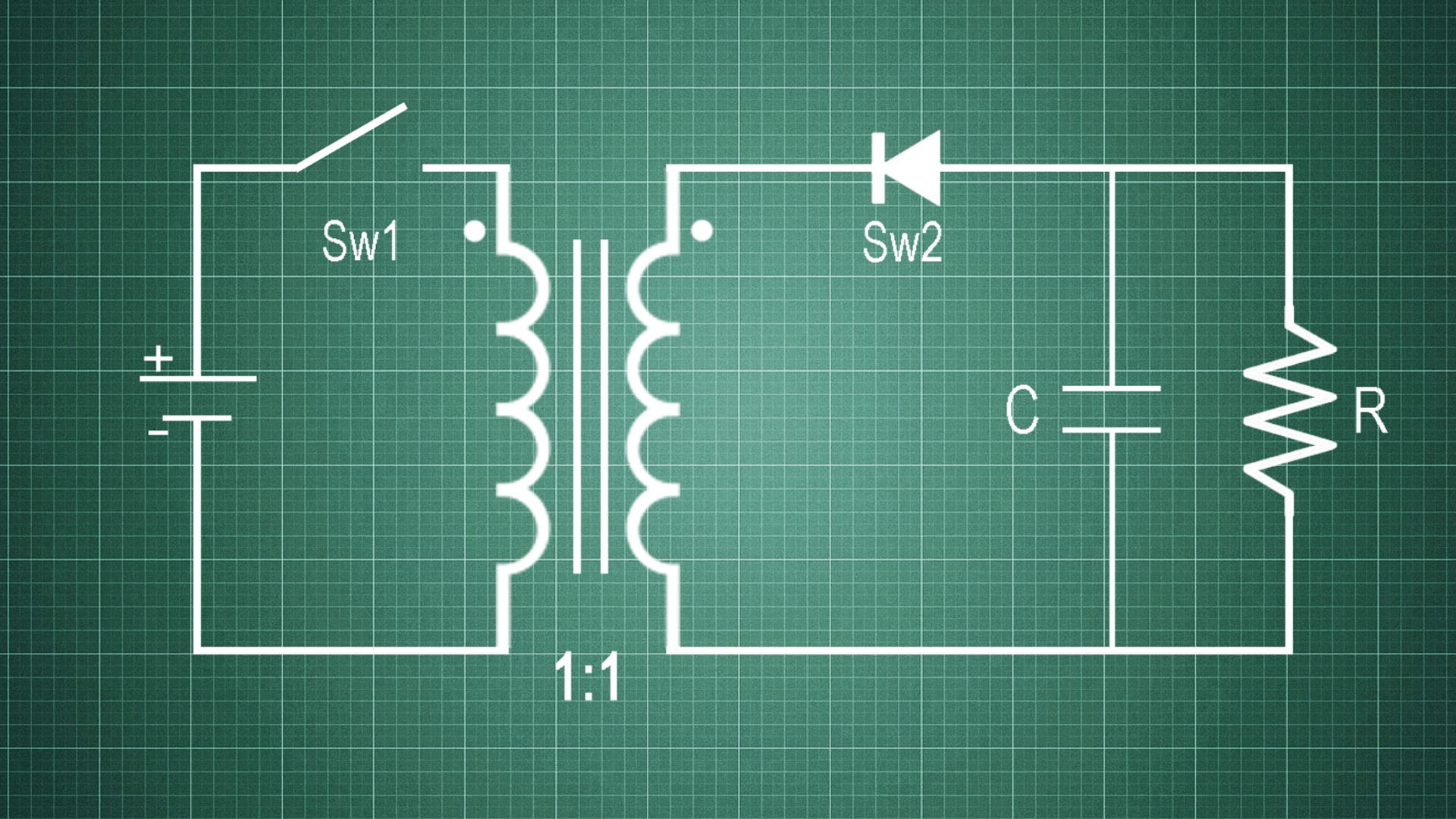
Now, when we open the first switch, the field will collapse. If the current in the primary was going into the dot like this, the current in the secondary will now go into the second dot like this, so the current flow is now available and we have a voltage drop on the load in this direction. That’s how we get rid of the second switch with the use of a diode. To get a positive voltage, what we do is to invert the secondary coil, so now the dot will be at the bottom here, and invert the diode as well.
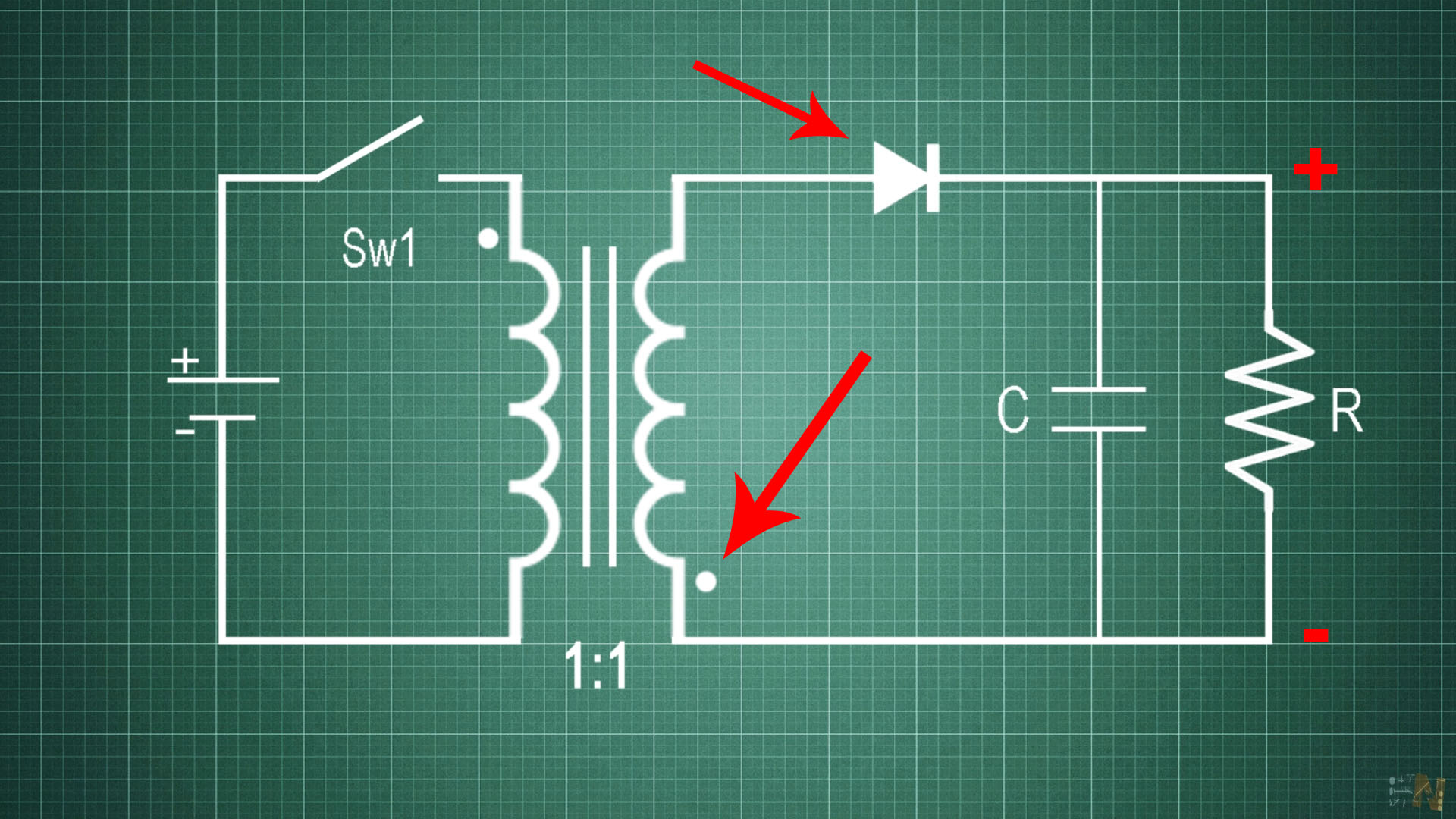
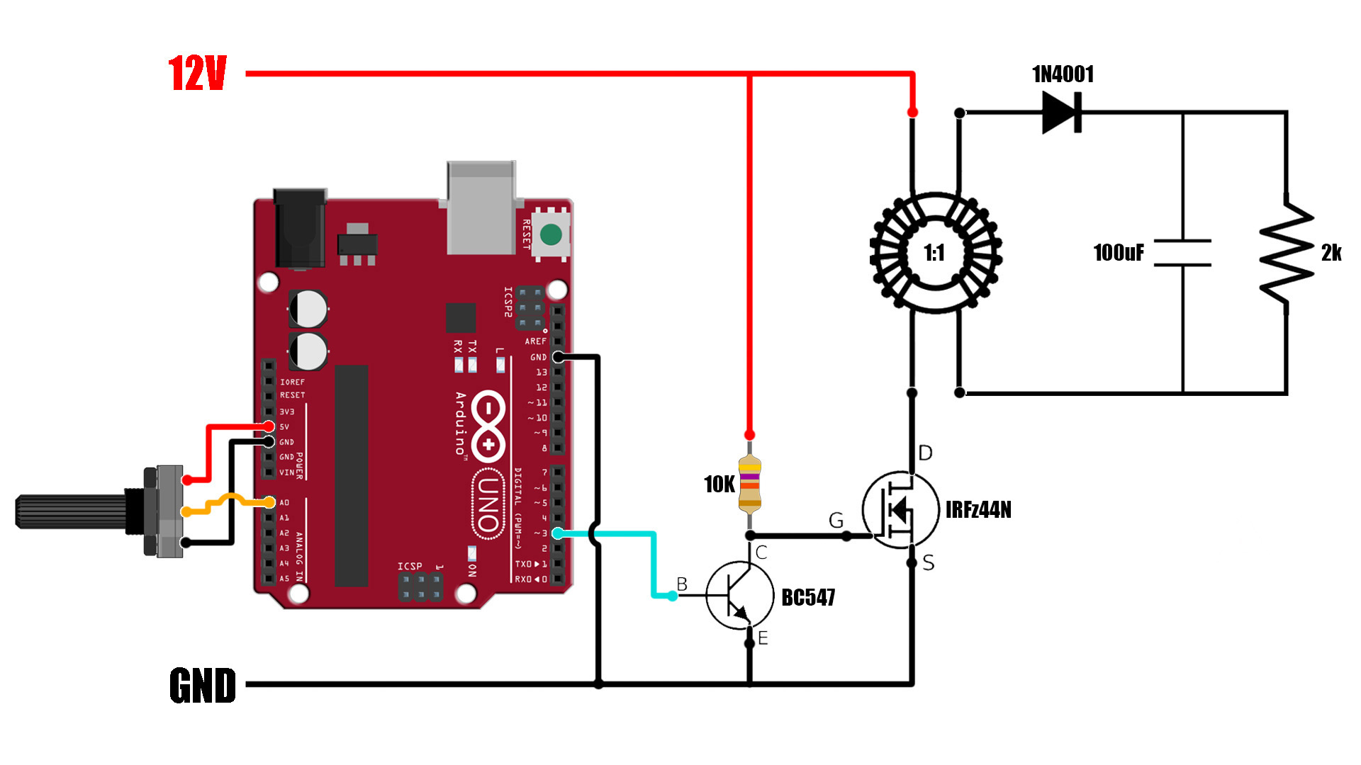
Now we will have a voltage at the output of this polarity. And if we add a capacitor, we could smooth the output and store the voltage, and basically that’s how the FLYBACK converter works. This time period will be given by the PWM signal we have seen before, that will control the switch. But in our example, the switch will be a MOSFET and connected like this to the primary winding. This is the schematic I’ve made for this experiment. The Arduino will control the Don and Doff times according to the potentiometer value.
The PWM signal is applied to a small BJT transistor that acts as a MOSFET driver and that is connected to the MOSFET gate. The MSOFET is our switch that will control the voltage to the primary coil. At the output we have the diode, capacitor and the load and as seen before, we can regulate the output voltage. I have 12V connected at the input. The inductor is a 1 to 1 ratio that’s why the output voltage could only go from the input value to lower values.
The code is just an example with no feedback. We read the value from the potentiometer and depending on that, we create a fast PWM signal and apply that to the BJT and then to the MOSFET. In this way we control the output voltage.
/* This is an example code for a Flyback converter with Arduino *
 * Subscribe: http://www.youtube.com/c/electronoobs
 * Tutorial: http://www.electronoobs.com/eng_circuitos_tut38_2.php
 */

int potentiometer = A0; //From the main potentiometer
int PWM = 3;


void setup() {
  pinMode(potentiometer, INPUT);
  pinMode(PWM, OUTPUT);
  TCCR2B = TCCR2B & B11111000 | B00000001;    // pin 3 and 11 PWM frequency of 31372.55 Hz
}

void loop() {
  float voltage = analogRead(potentiometer);
  int VALUE = map(voltage,0,1024,0,254);
  analogWrite(PWM,VALUE);
}
So, what advantages we have? First, we have isolation between the input and the output and that’s very important for safety. As you can see, there is no direct connection between the primary and secondary so high voltage could be on one side and low voltage on the other. For example, in a switch supply like this one, the main input is 230V and the output is 12V. Having a perfect isolation between these voltages is a very good safety feature.
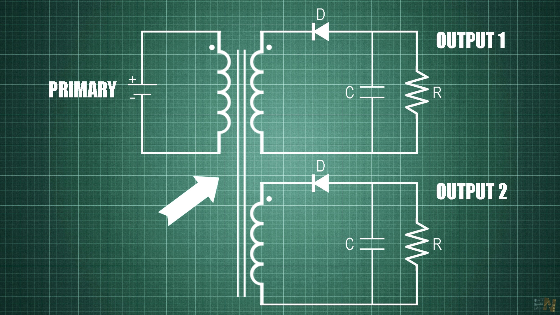
Another advantage is the use of multiple outputs. Remember that at the beginning we saw that this transformer had a lot of outputs. That’s because, to the same primary inductor, we could add multiple secondary coils with a different winding ratio. In case of two outputs, the energy that builds in the primary, will then divide for the two outputs and we could have different values at the output. We could even have one positive and one negative output, depending on the configuration. That’s why, switched power supplies with multiple outputs will have a big transformer with multiple windings.
Another advantage is that we could use this as a boost or buck converter since depending on the winding ratio, we could increase or decrease the voltage or do both at the same time.
A disadvantage of this converter is the output noise. Since we have discontinuous current at the input and output, that will create a ripple and the output voltage will have noise. But that is common with all switched voltage converters and we could just ignore it for everyday circuits. For more precise voltage values, you might want to look into other forms of regulating than switched supplies.