
Cool robot that follows black line. Learn and make a line follower robot with PID controller in 2 hours.
One feature that most rover autonomous robots need is line following. The purpose of this project is to build a line follower robot and get started on learning PID controller in a fun way.
The robot function properly with two motors, the Rosbot Baseboard, and a 5-Channel sensor. Unlike others, you don't have to buy extra H-bridge motor driver or various components since the Rosbot Baseboard has in-built 2x H-bridge dual driver. Simply connects motors to the Rosbot baseboard and it will supply more power than Arduino Uno.
Cool and solid chassis that has tons of mounting holes (4.8mm LEGO Technic), you can definitely reuse this chassis for other fun projects.
An Arduino UNO based mainboard with 2x on-board dual H-bridge motor drivers.
5-Channel Infrared detector, more accurate and stable.
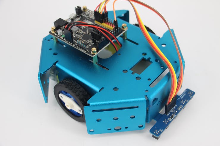
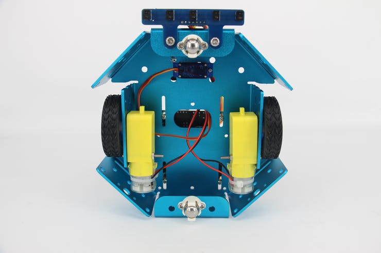
This robot is fairly easy to assemble, follow the instruction and it takes you about 15 minutes. First, attach your motors to the sides of chassis, simply plug in the rubber wheel. Mount the 5-Channel IR sensor to the front of the chassis. Attach your Rosbot baseboard to the chassis, then the robot is ready to get wired up.
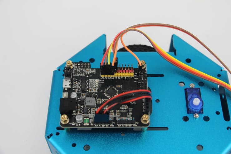
The following are the connections for 5-Channel IR sensor:
DC motors simply go to pin A+A- and pin B+B-.
In the codes, we have a state machine that indicates each possible sensor array output. The robot moves to a certain direction according to the sensor array output. We already set up the value of Error, proportion term, integral term, and derivative term. Manipulate the values to find the best fit for your robot.
#include <Adafruit_NeoPixel.h>
#define S_NULL 0
#define S_ONTRACE 1


Adafruit_NeoPixel pixels = Adafruit_NeoPixel(4, 4, NEO_GRB + NEO_KHZ800);


void doDcSpeed(int spdL, int spdR) {
  spdR = -spdR;
  if (spdL < 0) {
    analogWrite(5, 0);
    analogWrite(6, -spdL);
  } else {
    analogWrite(5, spdL);
    analogWrite(6, 0);
  }

  if (spdR < 0) {
    analogWrite(9, 0);
    analogWrite(10, -spdR);
  } else {
    analogWrite(9, spdR);
    analogWrite(10, 0);
  }
}

int bias = 0;
int outlineCnt = 0;

void stateMachine(int a) {
  switch (a) {
    case B00000:
      outlineCnt++;
      break;
    case B11111:
      outlineCnt++;
      break;
    case B00010:
    case B00110:
      outlineCnt = 0;
      pixels.setPixelColor(2, pixels.Color(0, 50, 0));
      bias = 1;
      break;
    case B00001:
    case B00011:
      outlineCnt = 0;
      pixels.setPixelColor(2, pixels.Color(0, 200, 0));
      bias = 2;
      break;
    case B00100:
      outlineCnt = 0;
      pixels.setPixelColor(2, pixels.Color(0, 0, 20));
      bias = 0;
      break;
    case B01000:
    case B01100:
      outlineCnt = 0;
      pixels.setPixelColor(2, pixels.Color(50, 0, 0));
      bias = -1;
      break;
    case B10000:
    case B11000:
      outlineCnt = 0;
      pixels.setPixelColor(2, pixels.Color(200, 0, 0));
      bias = -2;
      break;
    default:
      Serial.println(a,BIN);
      outlineCnt++;
      break;
  }

  pixels.setPixelColor(0, pixels.Color(outlineCnt * 10, 0, 0));
  if (outlineCnt > 10) {
    doDcSpeed(0,0);
  } else {
    float ff = 150;
    float ctrl = calcPid(bias);
    doDcSpeed(ff-ctrl,ff+ctrl);
  }
  pixels.show();
}

float Kp = 25;
float Ki = 0.15;
float Kd = 1200;
float error, errorLast, erroInte;

float calcPid(float input) {
  float errorDiff;
  float output;
  error = error * 0.7 + input * 0.3; // filter
  //error = input;
  errorDiff = error - errorLast;
  erroInte = constrain(erroInte + error, -50, 50);
  output = Kp * error + Ki * erroInte + Kd * errorDiff;
  Serial.print(error); Serial.print(' ');
  Serial.print(erroInte); Serial.print(' ');
  Serial.print(errorDiff); Serial.print(' ');
  Serial.println(output);
  errorLast = error;

  return output;
}

int echoTrace() {
  int ret = 0;
  int a[5];
  for (int i = 0; i < 5; i++) {
    a[i] = constrain((1025 - analogRead(A0 + i)) / 10 - 4, 0, 20);
    if (a[i] > 2) ret += (0x1 << i);
  }
  return ret;
}

void setup() {
  Serial.begin(115200);
  pixels.begin();
}

int pos;
void loop() {
  delay(5);
  pos = echoTrace();
  stateMachine(pos);

}


