So, I've made a video with some radio modules you could use. In this case we will see the HC12 radio module with UART serial communication. See the connections below, download the example code and test if it works. You need two modules, an LED and a potentiometer and we will send just one byte of data, 0 to 255 values. The range for this module could be up to 1.8Km and it has very few connections.
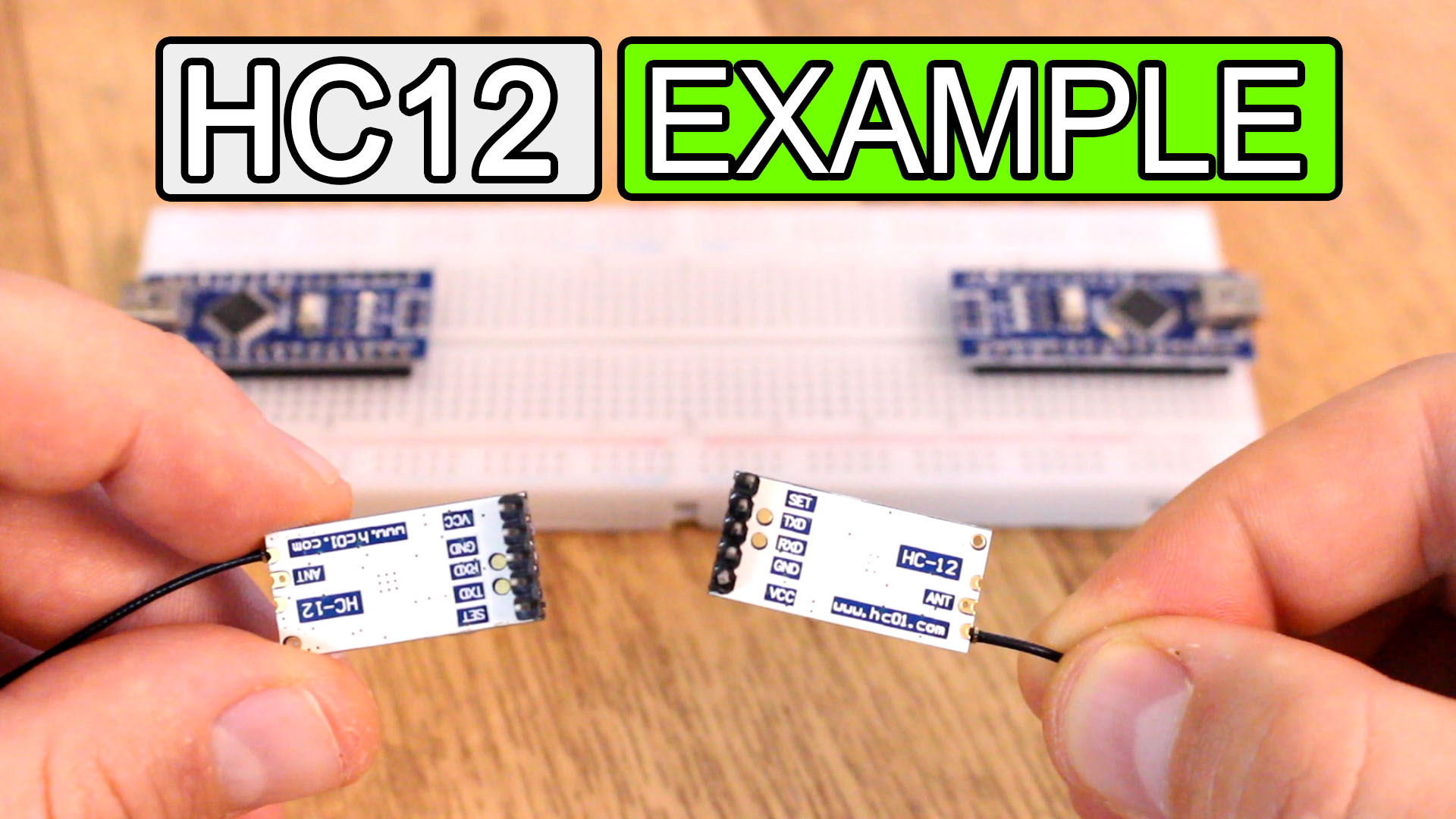
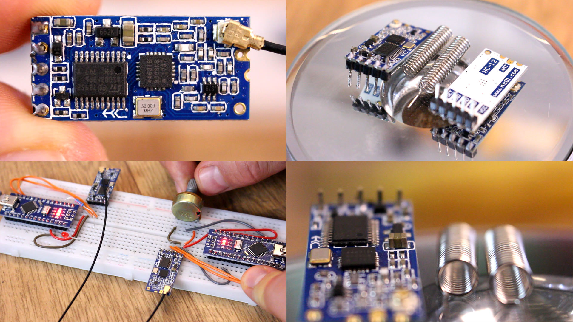
Now let’s see the HC12 radio module. This one is capable of making a long-range wireless communication between multiple Arduino boards, with distances up to 1.8km. First let’s take a closer look at the HC-12 wireless communication module. For that, here are some specification. The operating voltage of the module is from 3.2 V to 5.5 V and for more stable work it is recommended to use a decoupling capacitor and an external power supply. For today’s example I’ve used the PC USB as power supply and had no problems with it. The working frequency is between 433 and 473 MHz and could be divided in 100 channels of each 400KHz step in between. The maximum operating current is 100mA. In order to use it we have a UART serial communication. The factory baud rate of the serial communication is 9600 bauds per second but you could increase that up to 115 200 bauds. To configure this module, you will have to use the AT commands and change the baud rate, change the channel from 1 to 100 or change the transmission mode and more. Here you have a table with all the AT commands for this module.
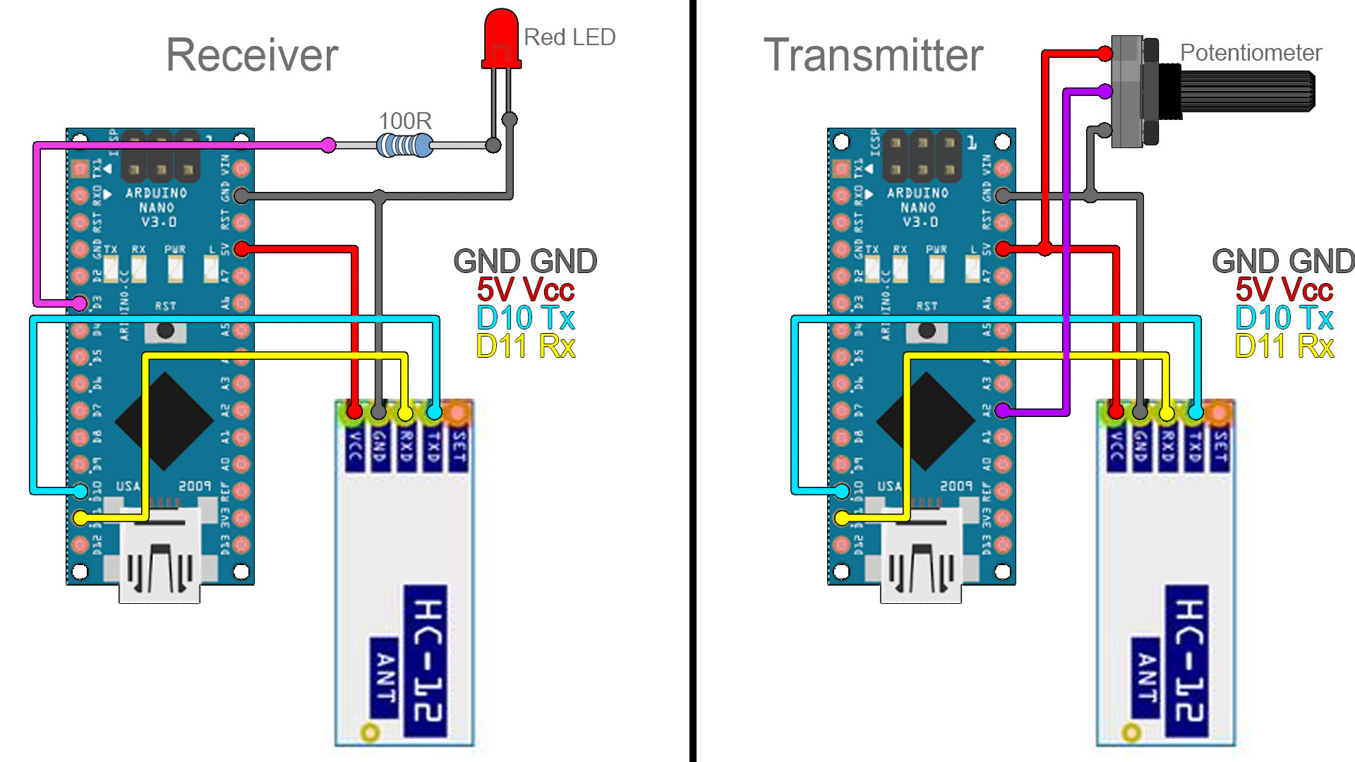
Ok, so connect these modules to the Arduino as in this schematic below. The code is more than simple since all we have to do is to use the serial communication just as if we were to print the values to the serial monitor of the Arduino. Download the code from below with the name HC 12 example for receiver and transmitter. Once again, upload the transmitter code to the Arduino with the potentiometer and the other code to the one with the LED and as you will see, I can send the analog value and control the brightness of the LED using a radio connection.
The schematic is simple. We have 2 Arduino NANO and we will use 5V from the Arduino in this case. If this doesn't work, connect an external 5V supply and share ground. Anyway, connect the UART Rx and Tx pins and add a potentiometer, and LED and a resistor. Upload the codes below to the transmitter and receiver and read the comments in the code for more. Test if it works and you could change the brightness of the LED using the radio connection.
Here we have the transmitter code. You don't need a library for this module. Uplaod this code to the Arduino with the potentiometer. Read the comments in the code for more. Copy or download the code from below.
/* 1byte HC12 TRANSMITTER example.
/* Tutorial link: http://electronoobs.com/eng_arduino_tut96.php
 * Code: http://electronoobs.com/eng_arduino_tut96_code1.php
 * Scheamtic: http://electronoobs.com/eng_arduino_tut96_sch1.php
 * Youtube Channel: http://www.youtube/c/electronoobs
 *
  Module // Arduino UNO/NANO
    GND    ->   GND
    Vcc    ->   3.3V
    Tx     ->   D10
    Rx     ->   D11
 */
#include <SoftwareSerial.h>
SoftwareSerial HC12(10, 11); // HC-12 TX Pin, HC-12 RX Pin
int pot = A2;
void setup() {
  Serial.begin(9600);             // Serial port to computer
  HC12.begin(9600);               // Serial port to HC12
  pinMode(pot,INPUT);
}
void loop() {
  int val = map(analogRead(pot),0,1024,0,255);
  HC12.write(val);      // Send that data to HC-12
}
Here we have the receiver code now. Uplaod this code to the Arduino with the LED. Read the comments in the code for more. Copy or download the code from below.
/* 1byte HC12 Receiver example.
/* Tutorial link: http://electronoobs.com/eng_arduino_tut96.php
 * Code: http://electronoobs.com/eng_arduino_tut96_code1.php
 * Scheamtic: http://electronoobs.com/eng_arduino_tut96_sch1.php
 * Youtube Channel: http://www.youtube/c/electronoobs
 *
  Module // Arduino UNO/NANO
    GND    ->   GND
    Vcc    ->   3.3V
    Tx     ->   D10
    Rx     ->   D11
 */
#include <SoftwareSerial.h>
SoftwareSerial HC12(10, 11); // HC-12 TX Pin, HC-12 RX Pin
int LED = 3;

void setup() {
  Serial.begin(9600);             // Serial port to computer
  HC12.begin(9600);               // Serial port to HC12
  pinMode(LED,OUTPUT);
}
void loop() {
  while (HC12.available()) {        // If HC-12 has data
    int val = HC12.read();
    Serial.println(HC12.read());      // Send the data to Serial monitor
    analogWrite(LED,val);
  }
}
Now you are able to control the LED using radio connection. These modules could get up to 1.8Km according to their datasheet. That's it for this module. I hope you are able to use it. If not, comment below and ask for help. Keep up!