
In a past tutorial that you could find on this link, we have seen how to make an Arduino based radio controller with multiple channels. Then, we have seen on this other tutorial, how to use that controller and move servos for a 3D printed turret. Is time to use the radio controller for something else, in this case make an RC car, or better said, an RC tank. This will have DC motors control, servos, sounds, radio and Bluetooth control and more...
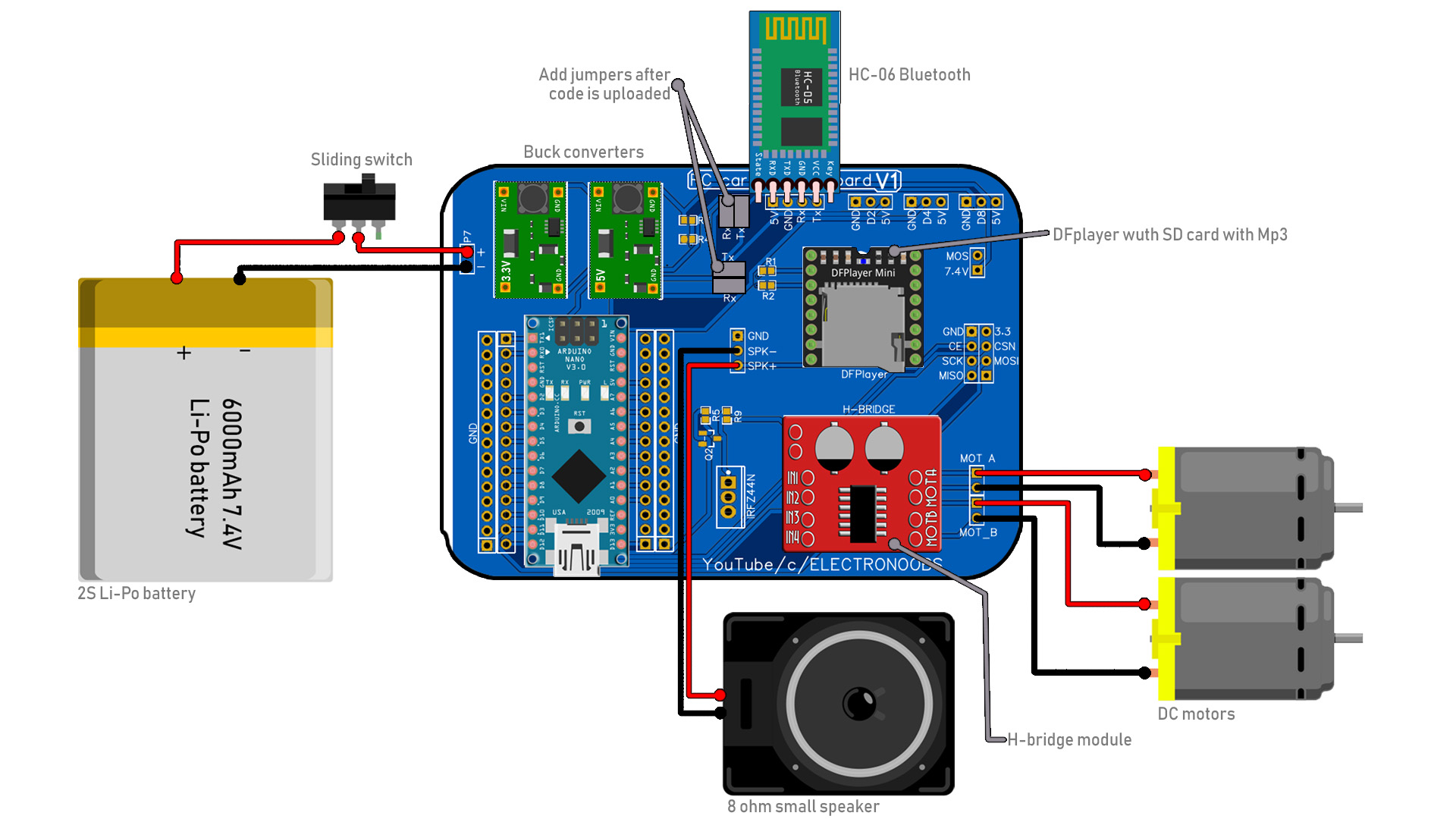
Below you have the schematic for this project. As you can see it is divided in a few blocks. First we have the Arduino block. I've placed two lines of extra female pins in case we want to connect something more to the Arduino. Then, we have the power block. To control servos, ESCs and more, we need good power. The Arduino voltage regulators for 5 and 3.3V are not that powerful. That's why I've used two small buck converters set to 3.3V and 5V. The main input is of a 2S battery of 7.4V. It can't be of 3S because the maximum voltage of the H-bridge is 9V. Also, have in mind that the DFplayer and Bluetooth module are using the UART port. That port is used to upload codes to the Arduino as well. So fot that I've placed jumpers. Remove the jumper, upload the code and place back the jumper.
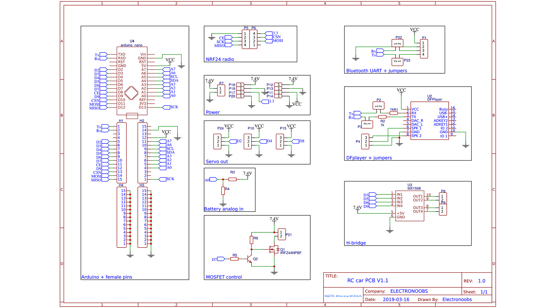
We can also see a voltage divider for the battery voltage measure. This can be used to monitor the battery value and maybe send it back to the radio controller. R3 and R4 have no value but a good one could be R3 equal to 20K and R4 equal to 10K, in this way the analog input would be of 7.4V/3 = 2.5V and the Arduino could read that. We have a DF player that could play Mp3 sounds, we have a spekaer output, an H-ridge that could control 2 DC motors, 3 servo or ESC outputs and a MOSFET output to control anythig we want.
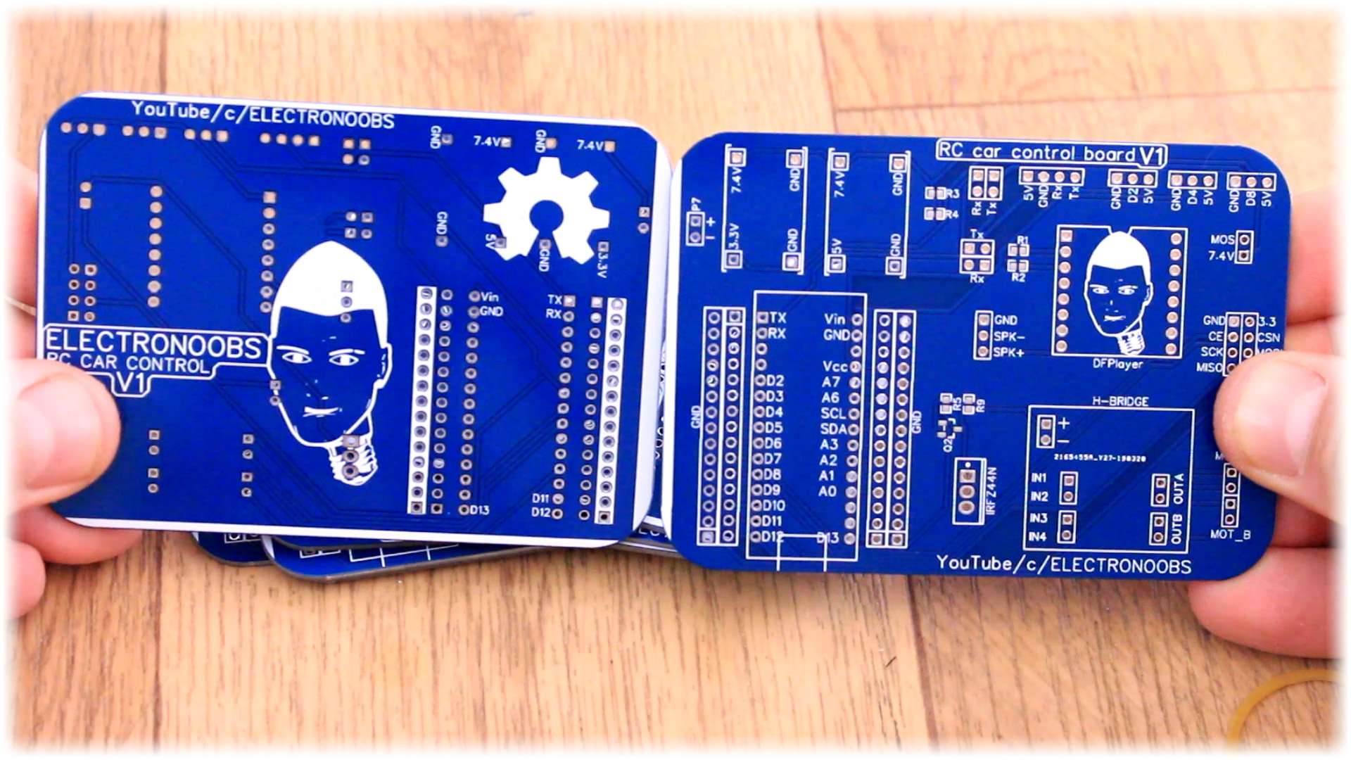
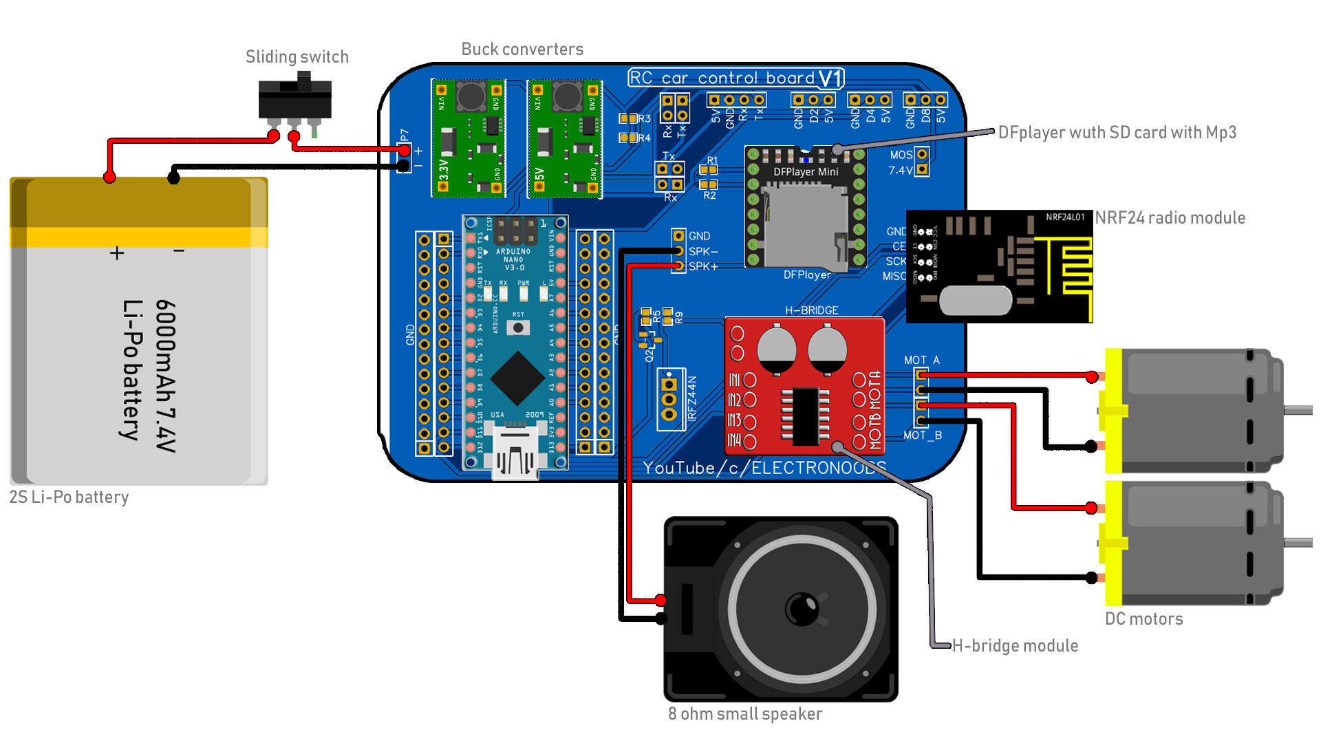
This is the design of my PCB. If you want to make it, you can download the GERBER file from below, send it to a manufacturing company and get the PCB. As you can see, it has labels for all the connections. For the 3.3 and 5V bucck converters, for the Bluetooth, radio and all the other modulkes. I've used female pins for all the connections so I would be able to remove the modules any time I want. You have outputs for all the modules: for the motors, speaker, servos, MOSFET, etc. You can use this board with radio using the NRF24 module or with Bluetooth with the HC-06 module and an Android App.
#include <SPI.h>
#include <nRF24L01.h>   //Download it here: https://www.electronoobs.com/eng_arduino_NRF24_lib.php
#include <RF24.h>
#include <Servo.h>      //To create PWM signals we need this lybrary
#include <SoftwareSerial.h>
#include <DFPlayer_Mini_Mp3.h>    //Downlaod it here: https://www.electronoobs.com/eng_arduino_tut22_code5.php
if(Serial.available()>0)
{
  Received = Serial.read();
  //char Rec = char(Received);
  //Serial.println(Received); //This is to visualise the received character
}


