
Now the code is a bit long and difficult to understand. That's why each line has a comment. So download the code from the link below. Then read each line in order to understand why I do each part. The code will have the main.ino but also s secondary code for the EEPROM write/read. The code starts by defining the variables to use in the code. In the Setup loop we first check if the first position of the EEPROM memory is 1. If not that means it is the first time we run the code so we save the min and max values of the PWM input signal and also write a "1" on the first EEPROM adress.
//This will only run once after you uplaod the code
  if( EEPROM.read(1) != 1)
  {
    EEPROM_writeAnything(PWM_IN_MIN_ADRESS, PWM_IN_MIN);
    EEPROM_writeAnything(PWM_IN_MAX_ADRESS, PWM_IN_MAX);
    EEPROM.write(1, 1);
  }
Then, still in the Setup loop we configure all the registers. We set the pins as outputs/inputs, we set the PWM registers and alos set digital pin D8 to be able to create pin state change interrumptions. This pin is used to read the input PWM width in microseconds.
 DDRD  |= B00011100;           // Configure pins 2, 3 and 4 as outputs
  PORTD  = B00000000;           //pins 0 to 7 set to LOW
  DDRB  |= B00001110;           // Configure pins 9, 10 and 11 as outputs
  PORTB  &= B00110001;          //B00110001    D9, D10 and D11 to LOW
  // Timer1
  TCCR1A = 0;
  TCCR1B = 0x01;
  // Timer2
  TCCR2A = 0;
  TCCR2B = 0x01;
  // Comparator on pin D6
  ACSR   = 0x10;           // Clear flag comparator interrupt
  //Set D8 (PWM in) to trigger interrupt (we use this to read PWM input)
  PCICR |= (1 << PCIE0);    //enable PCMSK0 scan
  PCMSK0 |= (1 << PCINT0);  //Set pin D8 trigger an interrupt on state change.
After the register configuration there are some loops that will detect if the ESC should enter configuration mode or not. If the input PWM signal is above a certain value when the ESC is powered on, then it should enter config mode where you could set the max and min range of the PWM input. If not, it will jump to the motor rotation loop.
 //Power on mode select
  if(PWM_INPUT > PWM_IN_MIN + 115)  //We enter config mode to set the PWM range
  {
     ESC_MODE_ON = false;           //Motor rotation is OFF till the config mode is done
    while(!PWM_RANGE_SET)
    {
    .
    .
    .
Then we have a bunch of functions and ISRs to detect the PWM input value, to change the pins for the MOSFET drivers to high or low or to PWM or not PWM and also to change the comparator input on pin D6. With this input we read the BEMF and on each step of the sequence we need to change that input from BEMF_A, to BEMF_B or BEMF_C. The Armega328 has this comparator on pin D6. The negative input if this comparator will be the COM line, which is the summ of all back electromotive foces of A, B and C. Then the positive input of the comparator will then be selected in the code with the line:
 void BEMF_A_RISING(){
  ADCSRA = (0 << ADEN);     // Disable the ADC module
  ADCSRB = (1 << ACME);     // Enable MUX select for negative input of comparator
  ADMUX = 2;                // Select A2 as comparator negative input
  ACSR |= 0x03;             // Set interrupt on rising edge*/
}
    .
    .
    .
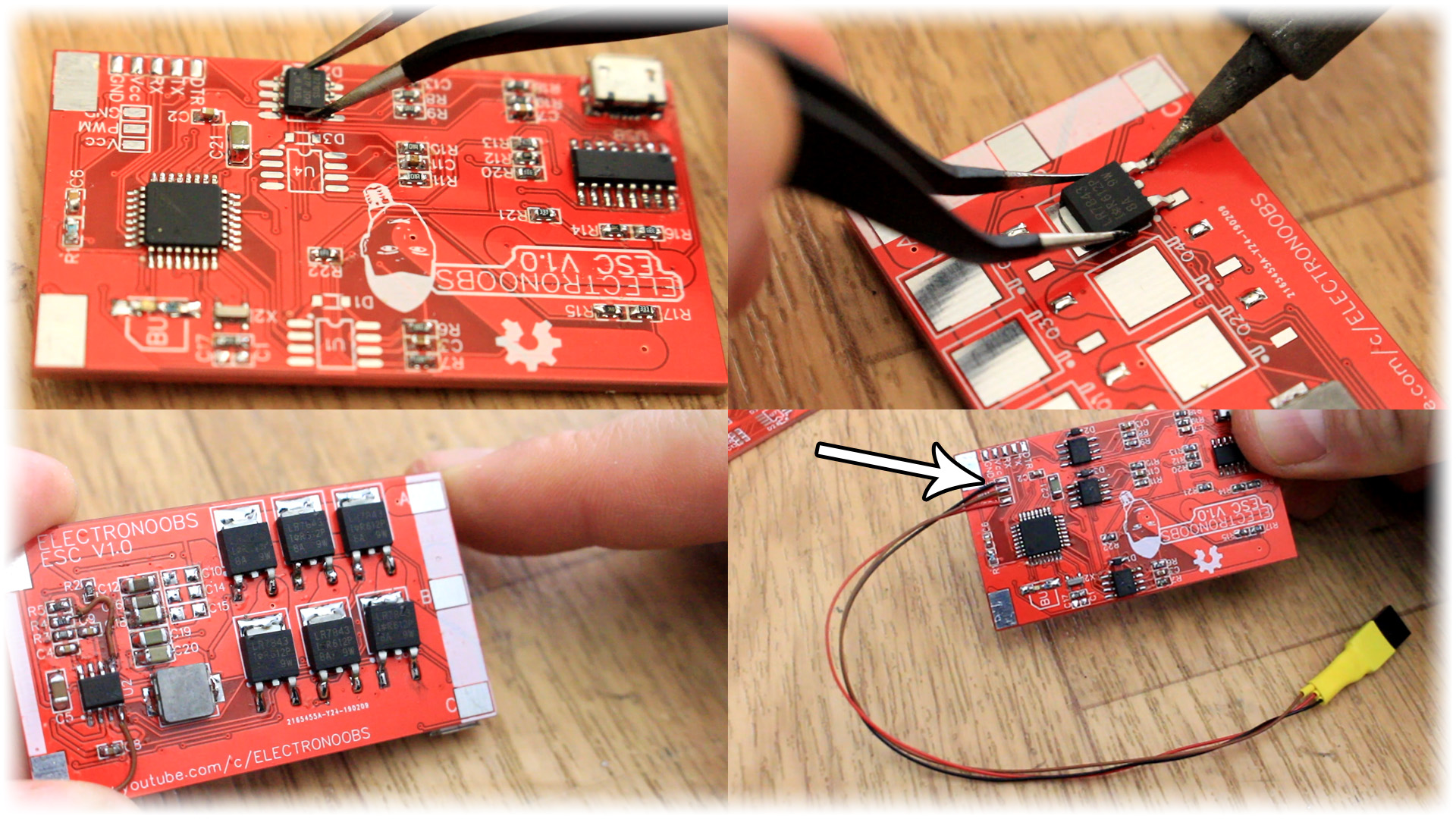
Please read the code for more details. Compile and upload it to the board. Now we can connect a brushless motor phase ouptput and test it. After you connect the motor apply 12V at the input and connect a PWM radio receiver to the PWM pins.
Once you uploaded the code and connected power, the motor and the PWN input we can test this. Make sure the PWM joystick is low and then connect power. When you increase the PWM signal the motor should spin. If you want to set a new range of PWM and calibrate the ESC, just put the joystick in the middle position before powering the ESC. Power the ESC and you will hear the config beeps. After the beeps put the joystick to the maximum value and then to the minimum value and it will get stored to the EEPROM. That's it.


