


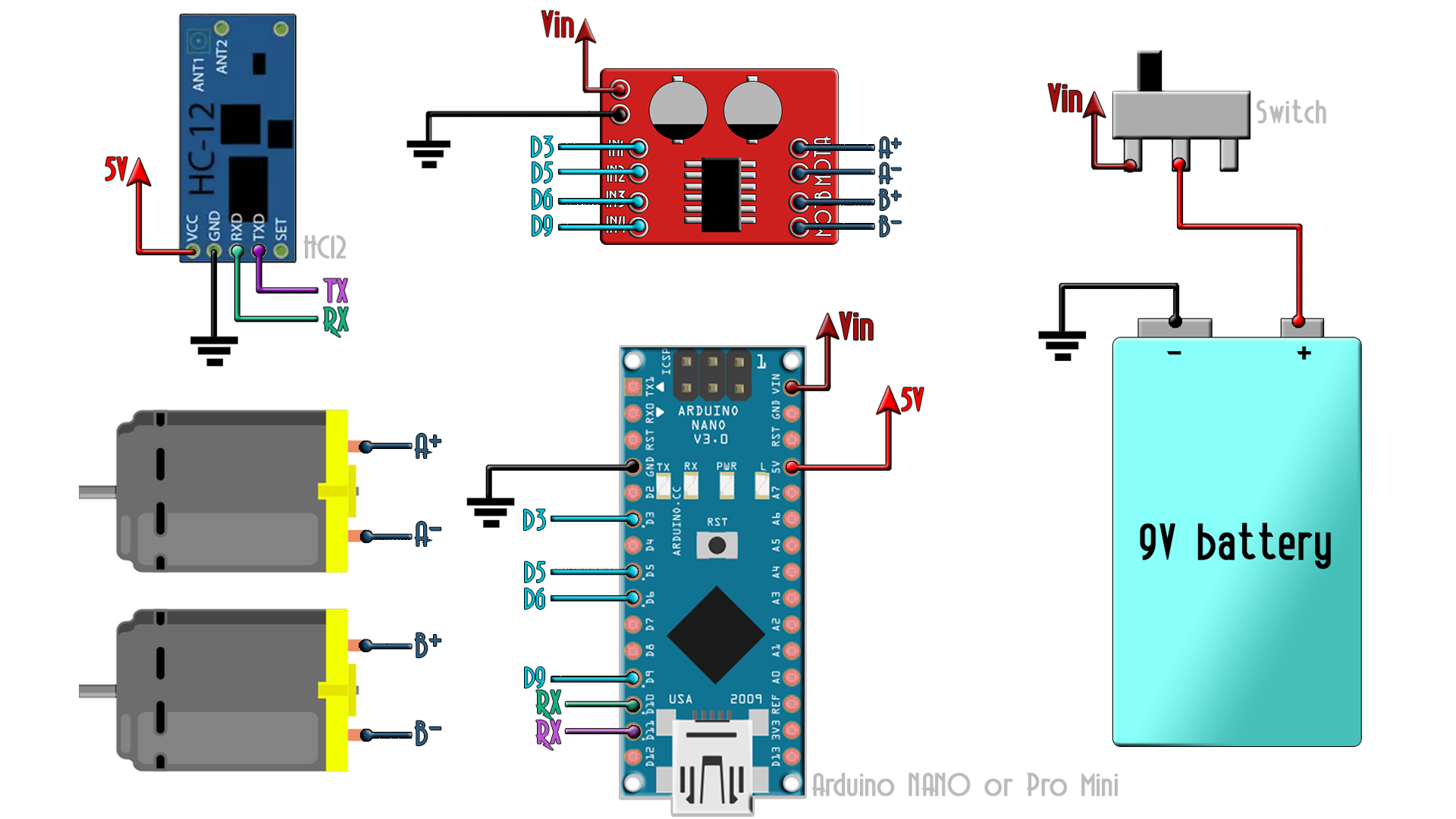
Download the .zip file below. Extract it and open the code in Arduino IDE. Make the connections as in the schematic, select the COM and uplaod the code to the receiver. Now it will sreceiver the angle and create PWM signals to the H-bridge. "
/* YouTube channel. http://www.youtube.com/c/electronoobs *
 * This is an example where get the data of the MPU6050
 * and send it using the HC12 radio module.
 * Schematic: https://www.electronoobs.com/eng_arduino_tut44_sch2.php
 * Tutorial: https://www.electronoobs.com/eng_arduino_tut44.php
 */
//Libraries
#include <SoftwareSerial.h>
SoftwareSerial HC12(11, 10);              // D11 is HC-12 TX Pin, D10 is HC-12 RX Pin

//////////////////////////////////////////////////////////////////////////////////////////////////////////////////////
//////////////////////////////////////////////////////////////////////////////////////////////////////////////////////

//Inputs and outputs
int pwm_front = 3;
int pwm_back = 5;
int pwm_left = 6;
int pwm_right = 9;


//Used variables for receive data and control motors
byte incomingByte;
String readBuffer = "";
String readBufferX = "";
String readBufferY = "";
int X_val = 0;
int Y_val = 0;
int i = 0;
bool x_ready = false;
bool y_ready = false;
bool x_passed = false;
bool data_received = false;
int pwm_x = 0;
int pwm_y = 0;


void setup() {
  Serial.begin(9600);                     // Open serial port
  HC12.begin(115200);                     // Open serial port to HC12
  pinMode(pwm_front,OUTPUT);              //Define the pins as outputs
  pinMode(pwm_back,OUTPUT);
  pinMode(pwm_left,OUTPUT);
  pinMode(pwm_right,OUTPUT);
  digitalWrite(pwm_front,LOW);            //Set the pins to low
  digitalWrite(pwm_back,LOW);
  digitalWrite(pwm_left,LOW);
  digitalWrite(pwm_right,LOW);
 }


void loop() {
  //First we store the entire incoming data into "readBuffer"
  while (HC12.available()> 0) {             // If the HC-12 has data in
    incomingByte = HC12.read();             // Store the data byte by byte
    readBuffer += char(incomingByte);       // Add each byte to ReadBuffer total string variable
  }
  delay(100); //This delay has to be equal or higher than the dalay in transmitter

  /*
  We know we first send the X angle data then the Y. So we store the number till
  we receive an "X". If "X" is received we stop adn we then get the x angle data
  till we receive an "Y".
  */
  while (i <= sizeof(readBuffer))
  {
    if(readBuffer[i] == 'X')
    {      x_ready = true;    }
    if(readBuffer[i] == 'Y')
    {      y_ready = true;    }
    if(!x_ready)
    {      readBufferX = readBufferX + (readBuffer[i] );    }
    if(x_passed && !y_ready)
    {      readBufferY = readBufferY + (readBuffer[i] );    }
    if(x_ready)
    {      x_passed = true;    }
    i=i+1;
  }
  data_received = true;

  X_val = readBufferX.toInt(); //Pass the data from string to int so we could use it
  Y_val = readBufferY.toInt();

  if(data_received)
  {
    ///////////////////////////////////////////////////////////////////////////
    //Uncomment the lines below if you want to print the data on serial monitor
    //Serial.print(X_val);
    //Serial.print("  ");
    //Serial.println(Y_val);
    ///////////////////////////////////////////////////////////////////////////

    //Now we reset all variables
    readBuffer = "";       //Reset the buffer to empty
    readBufferX = "";       //Reset the buffer to empty
    x_ready = false;        //Reset the other values
    x_passed = false;
    readBufferY = "";       //Reset the buffer to empty
    y_ready = false;
    i=0;
  }
  data_received = false;

///////////////////////////////////////////////////////////////////////////
////////////////////////////front and back/////////////////////////////////
///////////////////////////////////////////////////////////////////////////
  //Now we control the PWM signal for each motor only if the angle of the
  //controller is higher ol lower than - 4
  if(X_val > 4)
  {
    pwm_x = map(X_val,0,35,0,200);    //Map the angle to a PWM signal from 0 tow 255
    constrain(pwm_x,0,200);           //Constrain the values
    analogWrite(pwm_front,pwm_x);     //Write the PWM signal and activate the motor
    analogWrite(pwm_back,LOW);
  }
  //We do the same for all 4 PWM pins
  if(X_val < -4)
  {
    pwm_x = map(X_val,0,-35,0,200);
    constrain(pwm_x,0,200);
    analogWrite(pwm_front,LOW);
    analogWrite(pwm_back,pwm_x);
  }

  if(X_val > -4 && X_val < 4)
  {
    analogWrite(pwm_front,LOW);
    analogWrite(pwm_back,LOW);
  }

///////////////////////////////////////////////////////////////////////////
////////////////////////////left and right/////////////////////////////////
///////////////////////////////////////////////////////////////////////////

  if(Y_val > 10)
  {
    analogWrite(pwm_right,200);
    analogWrite(pwm_left,LOW);
  }

  if(Y_val < -10)
  {
    analogWrite(pwm_right,LOW);
    analogWrite(pwm_left,200);
  }

  if(Y_val > -10 && Y_val < 10)
  {
    analogWrite(pwm_right,LOW);
    analogWrite(pwm_left,LOW);
  }
///////////////////////////////////////////////////////////////////////////
///////////////////////////////////////////////////////////////////////////
}//End of void loop


