@tutorial:
MPU Gyro radio controller with Arduino and HC12 radio
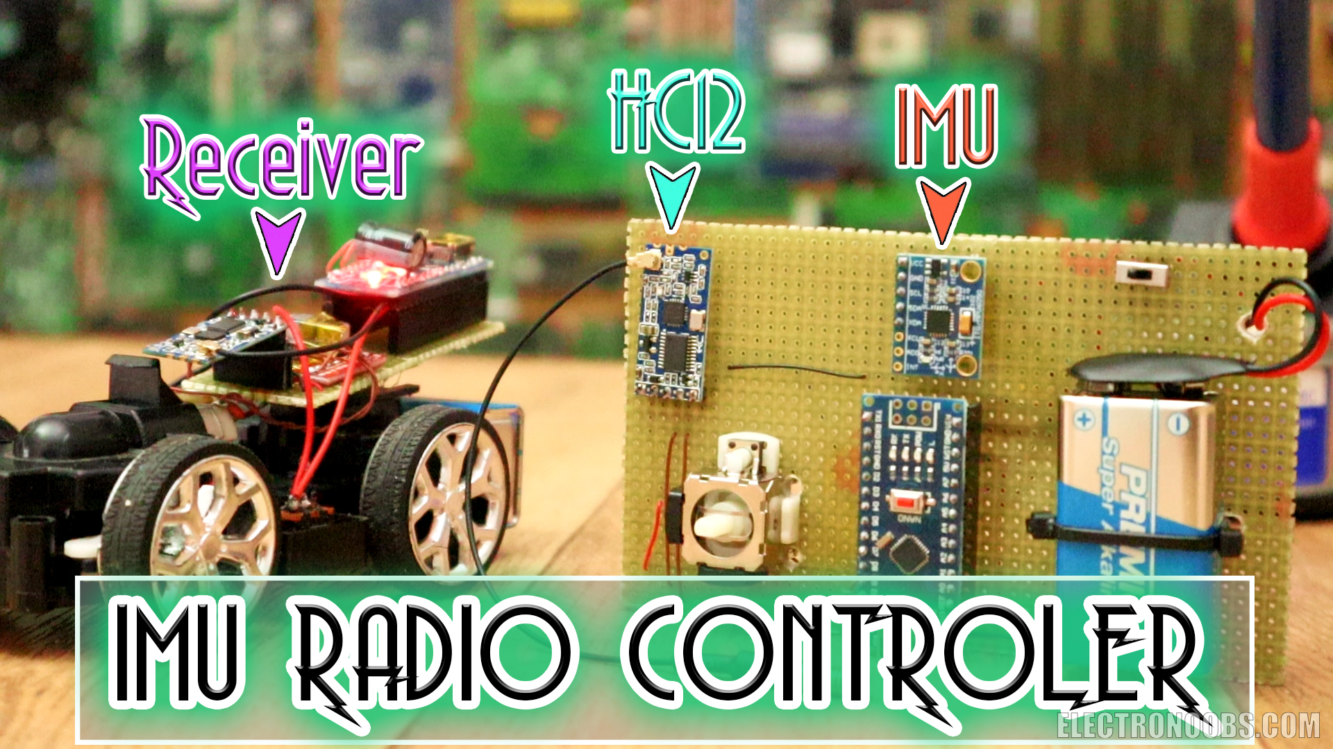
This is a radio controller that has 2 analog channels and the data is out from a MPU6050 gyro module. So, we could control a toy car for example just by rotating the controller. I usually use the NRF24 module, but in this project I also want to show you how to use the HC12 module. You will learn how to get the IMU data, how to use the HC12 radio connection and how to control 2 DC motors using PWM signals and an H-bridge.
by: ELECTRONOOBS on 2026-09-22
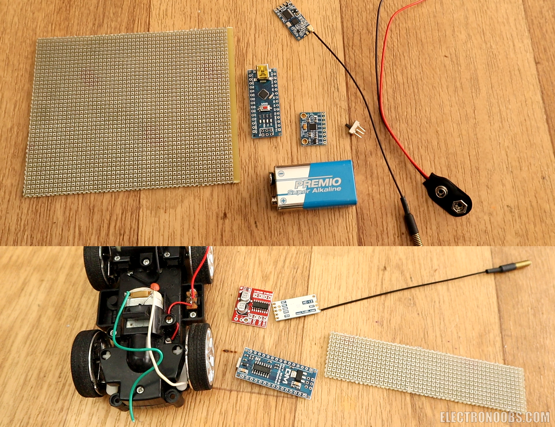
The radio transmitter is simple. In the middle we haev the MPU6050 gyro mdoule so we could detect the angle of the controller. To control everything we have the Arduino NANO and as a supply, I'll use a 9V battery connected to a sliding switch so we could turn the controller ON/OFF. I also have a Joystick, but we won't use that in this first part of the tutorial, we will add 2 more channels later with that joystick. Finally, to send the data, i'll use the HC12 radio mdoule that uses a serial UART communication. It seems to have a better range than the NRF24 mdoules.
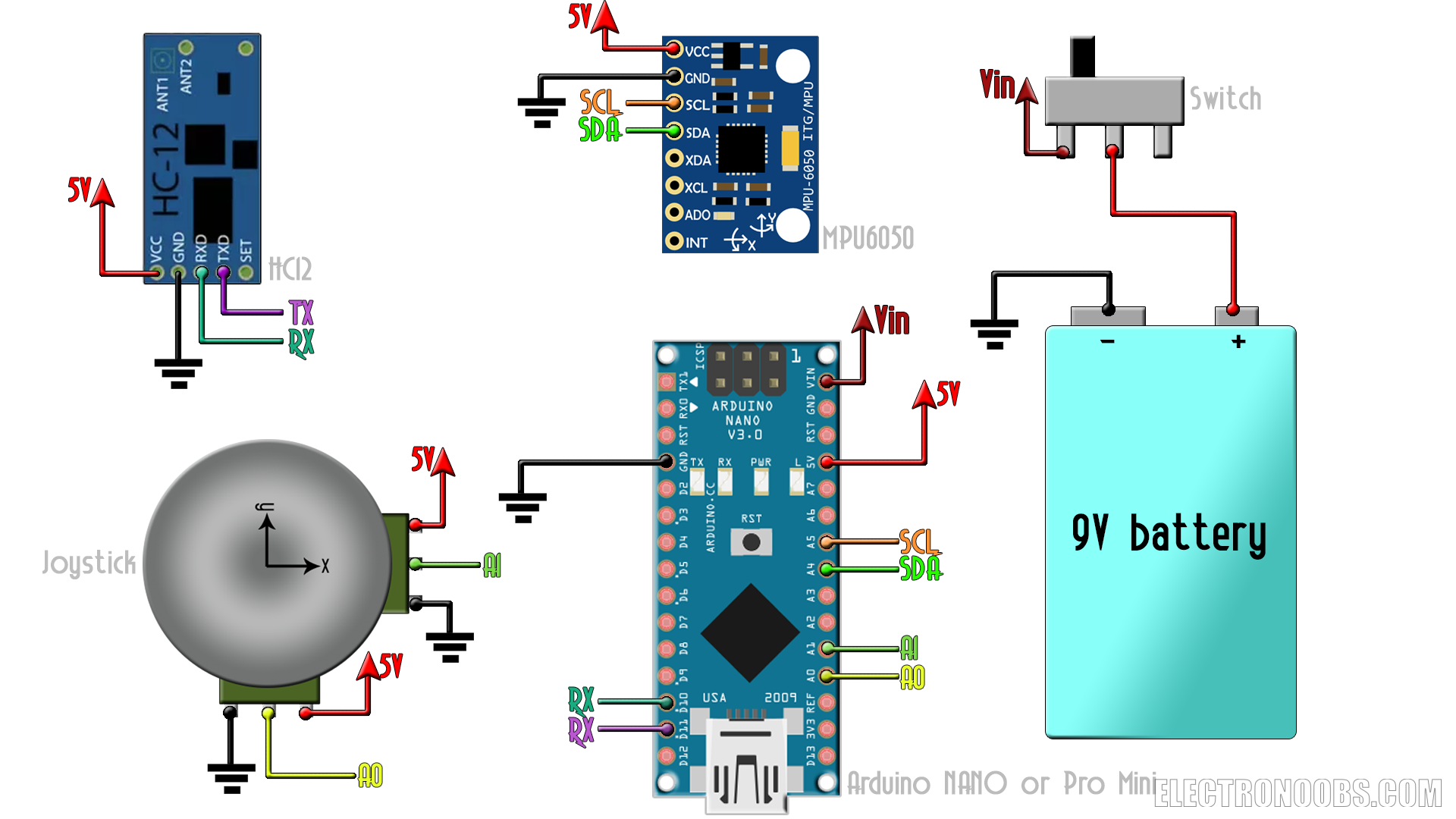
Transmitter code
Now that we have the schematic, is time to code the transmitter. What I want is to read the X and Y angles and then send the data to the receiver. Maping the angles to a PWM signal shoudl control motors, LEDs, etc. So the first step is to read the Gyro and Accelerations data and get the real angles.
/* YouTube channel. http://www.youtube.com/c/electronoobs *
 * This is an example where get the data of the MPU6050
 * and send it using the HC12 radio module.
 * Schematic: https://www.electronoobs.com/eng_arduino_tut44_sch1.php
 * Tutorial: https://www.electronoobs.com/eng_arduino_tut44.php
 */
//Libraries
#include <Wire.h>
#include <SoftwareSerial.h>
SoftwareSerial HC12(11, 10);              // D11 is HC-12 TX Pin, D10 is HC-12 RX Pin

//////////////////////////////////////////////////////////////////////////////////////////////////////////////////////
//////////////////////////////////////////////////////////////////////////////////////////////////////////////////////

//Variables for the Gyro data
float elapsedTime, time, timePrev;        //Variables for time control
int gyro_error=0;                         //We use this variable to only calculate once the gyro data error
float Gyr_rawX, Gyr_rawY, Gyr_rawZ;     //Here we store the raw data read
float Gyro_angle_x, Gyro_angle_y;         //Here we store the angle value obtained with Gyro data
float Gyro_raw_error_x, Gyro_raw_error_y; //Here we store the initial gyro data error

//Variables for acceleration data
int acc_error=0;                         //We use this variable to only calculate once the Acc data error
float rad_to_deg = 180/3.141592654;      //This value is for pasing from radians to degrees values
float Acc_rawX, Acc_rawY, Acc_rawZ;    //Here we store the raw data read
float Acc_angle_x, Acc_angle_y;          //Here we store the angle value obtained with Acc data
float Acc_angle_error_x, Acc_angle_error_y; //Here we store the initial Acc data error
//Total angle data
float Total_angle_x, Total_angle_y;
//Data to send
int x_send, y_send;

//////////////////////////////////////////////////////////////////////////////////////////////////////////////////////
//////////////////////////////////////////////////////////////////////////////////////////////////////////////////////

void setup() {
  Serial.begin(9600);                     //Start serial com in order to print valeus on monitor
  HC12.begin(9600);                       //Start the HC12 serial communication at 9600 bauds. Change bauds if needed
  begin_MPU6050();                        //Call this function and start the MPU6050 module
  time = millis();                        //Start counting time in milliseconds
  calculate_IMU_error();                  //Call this function and het the acc and gyro error at the beginning
}//end of setup void


//////////////////////////////////////////////////////////////////////////////////////////////////////////////////////
//////////////////////////////////////////////////////////////////////////////////////////////////////////////////////

void loop() {
  timePrev = time;                            // the previous time is stored before the actual time read
  time = millis();                            // actual time read
  elapsedTime = (time - timePrev) / 1000;     //divide by 1000 in order to obtain seconds

  //////////////////////////////////////Gyro read/////////////////////////////////////

  Wire.beginTransmission(0x68);             //begin, Send the slave adress (in this case 68)
  Wire.write(0x43);                          //First adress of the Gyro data
  Wire.endTransmission(false);
  Wire.requestFrom(0x68,4,true);             //We ask for just 4 registers
  Gyr_rawX=Wire.read()<<8|Wire.read();      //Once again we shif and sum
  Gyr_rawY=Wire.read()<<8|Wire.read();
  /*Now in order to obtain the gyro data in degrees/seconds we have to divide first
  the raw value by 32.8 because that's the value that the datasheet gives us for a 1000dps range*/
  /*---X---*/
  Gyr_rawX = (Gyr_rawX/32.8) - Gyro_raw_error_x;
  /*---Y---*/
  Gyr_rawY = (Gyr_rawY/32.8) - Gyro_raw_error_y;
  /*Now we integrate the raw value in degrees per seconds in order to obtain the angle
  * If you multiply degrees/seconds by seconds you obtain degrees */
  /*---X---*/
  Gyro_angle_x = Gyr_rawX*elapsedTime;
  /*---X---*/
  Gyro_angle_y = Gyr_rawY*elapsedTime;


  //////////////////////////////////////Acc read/////////////////////////////////////

  Wire.beginTransmission(0x68);     //begin, Send the slave adress (in this case 68)
  Wire.write(0x3B);                 //Ask for the 0x3B register- correspond to AcX
  Wire.endTransmission(false);      //keep the transmission and next
  Wire.requestFrom(0x68,6,true);    //We ask for next 6 registers starting withj the 3B
  /*We have asked for the 0x3B register. The IMU will send a brust of register.
  * The amount of register to read is specify in the requestFrom function.
  * In this case we request 6 registers. Each value of acceleration is made out of
  * two 8bits registers, low values and high values. For that we request the 6 of them
  * and just make then sum of each pair. For that we shift to the left the high values
  * register (<<) and make an or (|) operation to add the low values.
  If we read the datasheet, for a range of+-8g, we have to divide the raw values by 4096*/
  Acc_rawX=(Wire.read()<<8|Wire.read())/4096.0 ; //each value needs two registres
  Acc_rawY=(Wire.read()<<8|Wire.read())/4096.0 ;
  Acc_rawZ=(Wire.read()<<8|Wire.read())/4096.0 ;
  /*Now in order to obtain the Acc angles we use euler formula with acceleration values
  after that we substract the error value found before*/
  /*---X---*/
  Acc_angle_x = (atan((Acc_rawY)/sqrt(pow((Acc_rawX),2) + pow((Acc_rawZ),2)))*rad_to_deg) - Acc_angle_error_x;
  /*---Y---*/
  Acc_angle_y = (atan(-1*(Acc_rawX)/sqrt(pow((Acc_rawY),2) + pow((Acc_rawZ),2)))*rad_to_deg) - Acc_angle_error_y;

  //////////////////////////////////////Total angle and filter/////////////////////////////////////
  /*---X axis angle---*/
  Total_angle_x = 0.98 *(Total_angle_x + Gyro_angle_x) + 0.02*Acc_angle_x;
  /*---Y axis angle---*/
  Total_angle_y = 0.98 *(Total_angle_y + Gyro_angle_y) + 0.02*Acc_angle_y;


   //Uncoment the next lines if you want to print the values on the serial monitor
   /*Serial.print("Xº: ");
   Serial.print(Total_angle_x);
   Serial.print("   |   ");
   Serial.print("Yº: ");
   Serial.print(Total_angle_y);
   Serial.println(" ");*/

  x_send = -Total_angle_x;  //pass from flaot to int in order to send the values, also invert X angle
  y_send = Total_angle_y;   //pass from flaot to int in order to send the values

  HC12.print(x_send);HC12.write("X"); //Send the x angle value and then the "X" character
  HC12.print(y_send);HC12.write("Y"); //Send the y angle value and then the "Y" character
  delay(50); //Add a delay of 50. This might affect the transmission
}//End of void loop


//////////////////////////////////////////////////////////////////////////////////////////////////////////////////////
//////////////////////////////////////////////////////////////////////////////////////////////////////////////////////


void begin_MPU6050()
{
  Wire.begin();                           //begin the wire comunication
  Wire.beginTransmission(0x68);           //begin, Send the slave adress (in this case 68)
  Wire.write(0x6B);                       //make the reset (place a 0 into the 6B register)
  Wire.write(0x00);
  Wire.endTransmission(true);             //end the transmission
  //Gyro config
  Wire.beginTransmission(0x68);           //begin, Send the slave adress (in this case 68)
  Wire.write(0x1B);                       //We want to write to the GYRO_CONFIG register (1B hex)
  Wire.write(0x10);                       //Set the register bits as 00010000 (1000dps full scale)
  Wire.endTransmission(true);             //End the transmission with the gyro
  //Acc config
  Wire.beginTransmission(0x68);           //Start communication with the address found during search.
  Wire.write(0x1C);                       //We want to write to the ACCEL_CONFIG register
  Wire.write(0x10);                       //Set the register bits as 00010000 (+/- 8g full scale range)
  Wire.endTransmission(true);
}


void calculate_IMU_error()
{
  /*Here we calculate the acc data error before we start the loop
 * I make the mean of 200 values, that should be enough*/
  if(acc_error==0)
  {
    for(int a=0; a<200; a++)
    {
      Wire.beginTransmission(0x68);
      Wire.write(0x3B);                       //Ask for the 0x3B register- correspond to AcX
      Wire.endTransmission(false);
      Wire.requestFrom(0x68,6,true);

      Acc_rawX=(Wire.read()<<8|Wire.read())/4096.0 ; //each value needs two registres
      Acc_rawY=(Wire.read()<<8|Wire.read())/4096.0 ;
      Acc_rawZ=(Wire.read()<<8|Wire.read())/4096.0 ;


      /*---X---*/
      Acc_angle_error_x = Acc_angle_error_x + ((atan((Acc_rawY)/sqrt(pow((Acc_rawX),2) + pow((Acc_rawZ),2)))*rad_to_deg));
      /*---Y---*/
      Acc_angle_error_y = Acc_angle_error_y + ((atan(-1*(Acc_rawX)/sqrt(pow((Acc_rawY),2) + pow((Acc_rawZ),2)))*rad_to_deg));

      if(a==199)
      {
        Acc_angle_error_x = Acc_angle_error_x/200;
        Acc_angle_error_y = Acc_angle_error_y/200;
        acc_error=1;
      }
    }
  }//end of acc error calculation


/*Here we calculate the gyro data error before we start the loop
 * I make the mean of 200 values, that should be enough*/
  if(gyro_error==0)
  {
    for(int i=0; i<200; i++)
    {
      Wire.beginTransmission(0x68);            //begin, Send the slave adress (in this case 68)
      Wire.write(0x43);                        //First adress of the Gyro data
      Wire.endTransmission(false);
      Wire.requestFrom(0x68,4,true);           //We ask for just 4 registers

      Gyr_rawX=Wire.read()<<8|Wire.read();     //Once again we shif and sum
      Gyr_rawY=Wire.read()<<8|Wire.read();

      /*---X---*/
      Gyro_raw_error_x = Gyro_raw_error_x + (Gyr_rawX/32.8);
      /*---Y---*/
      Gyro_raw_error_y = Gyro_raw_error_y + (Gyr_rawY/32.8);
      if(i==199)
      {
        Gyro_raw_error_x = Gyro_raw_error_x/200;
        Gyro_raw_error_y = Gyro_raw_error_y/200;
        gyro_error=1;
      }
    }
  }//end of gyro error calculation
}Read the IMU
To read the IMU data we will use i2c comunication so for that we need the wire library. That's why in the code we first inport that library adn also the SoftwareSerial library for the HC12 UART communication. Uisng the wire functions, as seen in the example below, we get the gyro and acc data. Then using the formulas and some filters we finally get the real angle from -90º to 90º for both X and Y axis.
Use the HC12 radio module
Now, the Arduino has a UART serial port on pins 0 and 1 which are the TX and RX pins. But we want to use different pins as a UART port. For taht we use the Software serial and create the TX and RX pins on digital pins of the ARduino D11 and D10. Now we could connect the HC12 to these pins and send data using the Serial.print() or Serial.write() functions.
Use the HC12 radio module
When you buy the HC12 module, it usually works at a baud rate of 9600. You could change that if you want using the code below. Make the connections as in the scheamtic below and also connect the set pin for this example. Without the set pin connected we can't put the module into config mode.
/*Code to change the HC-12 baud rate
 * Arduino  |   HC-12
  D11           TxD
  D10           RxD
  GND           GND
  GND           SET
  5V            VCC
*/
#include
SoftwareSerial hc12(11, 10);

void setup()
{
pinMode(7,OUTPUT);
digitalWrite(7,LOW); // enter AT command mode
Serial.begin(9600);
hc12.begin(9600);
hc12.print(F("AT+C001")); // set to channel 1
delay(100);
digitalWrite(7,LOW);// enter transparent mode
}
void loop()
{
if(Serial.available()) hc12.write(Serial.read());
if(hc12.available()) Serial.write(hc12.read());
}

/*
 * 1. Change Baud Rate:
Enter “AT+Bxxxx” to change baud rate to xxxx bps.
Example: Enter “AT+B19200” and the module will work at baud rate 19200 bps and return “OK+B19200”.
The available values of xxxx are: 1200, 2400, 4800, 9600, 19200, 38400, 57600, 115200.
The default baud rate is 9600 bps.
 * 2. Change Communication Channel:
Enter “AT+Cyyy” to change communication channel to yyy.
Example: Enter “AT+C021” and the module will change to channel 021 and return “OK+C021”.
The available values of yyy are: 001, 002, 003, …, 127.
The default channel is 001.
 * 3. Factory Reset:
Enter “AT+DEFAULT” and the module will reset to default settings and return “OK+DEFAULT”.
*/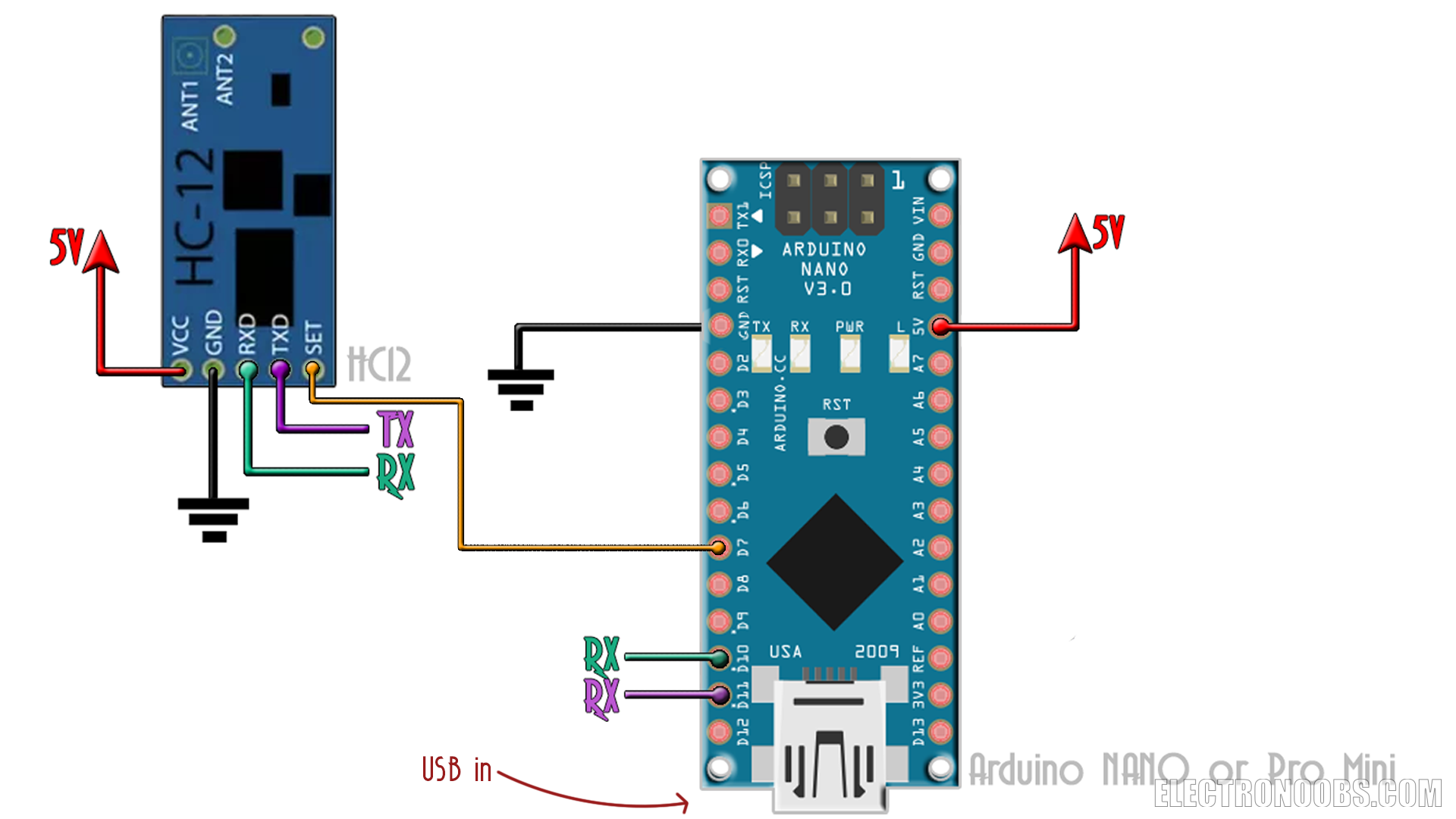
After you upload the code above, open serial monitor and in that window below, set the baud rate to 9600. Now type AT+___ where ____ is the command that you want. Below you ahve some examples. For example, to set the baud rate to 115200 type AT+B115200 and press enter and the new baud rate is set to the HC-12. That's it.
1. Change Baud Rate:
Enter “AT+Bxxxx” to change baud rate to xxxx bps.
Example: Enter “AT+B19200” and the module will work at baud rate 19200 bps and return “OK+B19200”.
The available values of xxxx are: 1200, 2400, 4800, 9600, 19200, 38400, 57600, 115200.
The default baud rate is 9600 bps.
2. Change Communication Channel:
Enter “AT+Cyyy” to change communication channel to yyy.
Example: Enter “AT+C021” and the module will change to channel 021 and return “OK+C021”.
The available values of yyy are: 001, 002, 003, …, 127.
The default channel is 001.
3. Factory Reset:
Enter “AT+DEFAULT” and the module will reset to default settings and return “OK+DEFAULT”.
Finally, in the code we use the HC12.write functions to send the X and Y data for the angles. First we send the "X" and "Y" character, so in the receiver we would be able to know which data is for the X and which for Y. We place a delay if 50ms after each data send. Make sure the receiver delay is superior to these 50ms.
Schematic
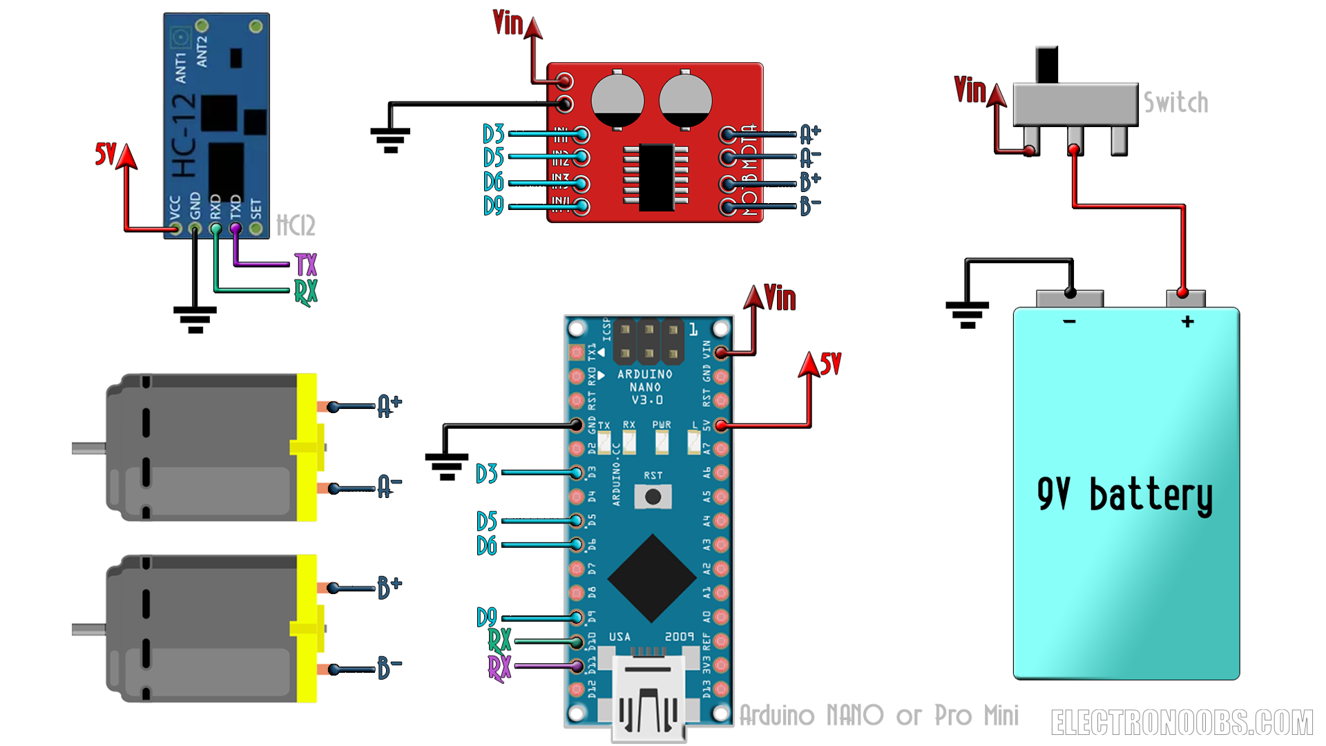
The radio receiver is also simple. We receive the data with the HC-12 module. Then we map the angles from -90 to 90 to a range of 0 to 200 PWM signal. That signal is applied to and H-bridge module that will control the speed and direction of rotaion ot two DC motors for our "toy car" example. As supply, once again, I'll use a 9V abttery connected to the Vin pin.
Receiver code
The code is simple as well. We need once again the SoftwareSerial library so we could get data from the HC12 module. We create 4 PWM signals to control the H-bridge. As we can see in the example below, we store the incoming bytes in a buffer than we will divide that buffer at the X and Y characters. For example, if we receive X23Y55 than we cut the X and Y and we get the 22º and 55º angles for each axis. Finally, we detect the range of the angles and change the value of the PWM signals, and by that control the car speed and direction of rotation of the motors.
/* YouTube channel. http://www.youtube.com/c/electronoobs *
 * This is an example where get the data of the MPU6050
 * and send it using the HC12 radio module.
 * Schematic: https://www.electronoobs.com/eng_arduino_tut44_sch2.php
 * Tutorial: https://www.electronoobs.com/eng_arduino_tut44.php
 */
//Libraries
#include <SoftwareSerial.h>
SoftwareSerial HC12(11, 10);              // D11 is HC-12 TX Pin, D10 is HC-12 RX Pin

//////////////////////////////////////////////////////////////////////////////////////////////////////////////////////
//////////////////////////////////////////////////////////////////////////////////////////////////////////////////////

//Inputs and outputs
int pwm_front = 3;
int pwm_back = 5;
int pwm_left = 6;
int pwm_right = 9;


//Used variables for receive data and control motors
byte incomingByte;
String readBuffer = "";
String readBufferX = "";
String readBufferY = "";
int X_val = 0;
int Y_val = 0;
int i = 0;
bool x_ready = false;
bool y_ready = false;
bool x_passed = false;
bool data_received = false;
int pwm_x = 0;
int pwm_y = 0;


void setup() {
  Serial.begin(9600);                     // Open serial port
  HC12.begin(115200);                     // Open serial port to HC12
  pinMode(pwm_front,OUTPUT);              //Define the pins as outputs
  pinMode(pwm_back,OUTPUT);
  pinMode(pwm_left,OUTPUT);
  pinMode(pwm_right,OUTPUT);
  digitalWrite(pwm_front,LOW);            //Set the pins to low
  digitalWrite(pwm_back,LOW);
  digitalWrite(pwm_left,LOW);
  digitalWrite(pwm_right,LOW);
 }


void loop() {
  //First we store the entire incoming data into "readBuffer"
  while (HC12.available()> 0) {             // If the HC-12 has data in
    incomingByte = HC12.read();             // Store the data byte by byte
    readBuffer += char(incomingByte);       // Add each byte to ReadBuffer total string variable
  }
  delay(100); //This delay has to be equal or higher than the dalay in transmitter

  /*
  We know we first send the X angle data then the Y. So we store the number till
  we receive an "X". If "X" is received we stop adn we then get the x angle data
  till we receive an "Y".
  */
  while (i <= sizeof(readBuffer))
  {
    if(readBuffer[i] == 'X')
    {      x_ready = true;    }
    if(readBuffer[i] == 'Y')
    {      y_ready = true;    }
    if(!x_ready)
    {      readBufferX = readBufferX + (readBuffer[i] );    }
    if(x_passed && !y_ready)
    {      readBufferY = readBufferY + (readBuffer[i] );    }
    if(x_ready)
    {      x_passed = true;    }
    i=i+1;
  }
  data_received = true;

  X_val = readBufferX.toInt(); //Pass the data from string to int so we could use it
  Y_val = readBufferY.toInt();

  if(data_received)
  {
    ///////////////////////////////////////////////////////////////////////////
    //Uncomment the lines below if you want to print the data on serial monitor
    //Serial.print(X_val);
    //Serial.print("  ");
    //Serial.println(Y_val);
    ///////////////////////////////////////////////////////////////////////////

    //Now we reset all variables
    readBuffer = "";       //Reset the buffer to empty
    readBufferX = "";       //Reset the buffer to empty
    x_ready = false;        //Reset the other values
    x_passed = false;
    readBufferY = "";       //Reset the buffer to empty
    y_ready = false;
    i=0;
  }
  data_received = false;

///////////////////////////////////////////////////////////////////////////
////////////////////////////front and back/////////////////////////////////
///////////////////////////////////////////////////////////////////////////
  //Now we control the PWM signal for each motor only if the angle of the
  //controller is higher ol lower than - 4
  if(X_val > 4)
  {
    pwm_x = map(X_val,0,35,0,200);    //Map the angle to a PWM signal from 0 tow 255
    constrain(pwm_x,0,200);           //Constrain the values
    analogWrite(pwm_front,pwm_x);     //Write the PWM signal and activate the motor
    analogWrite(pwm_back,LOW);
  }
  //We do the same for all 4 PWM pins
  if(X_val < -4)
  {
    pwm_x = map(X_val,0,-35,0,200);
    constrain(pwm_x,0,200);
    analogWrite(pwm_front,LOW);
    analogWrite(pwm_back,pwm_x);
  }

  if(X_val > -4 && X_val < 4)
  {
    analogWrite(pwm_front,LOW);
    analogWrite(pwm_back,LOW);
  }

///////////////////////////////////////////////////////////////////////////
////////////////////////////left and right/////////////////////////////////
///////////////////////////////////////////////////////////////////////////

  if(Y_val > 10)
  {
    analogWrite(pwm_right,200);
    analogWrite(pwm_left,LOW);
  }

  if(Y_val < -10)
  {
    analogWrite(pwm_right,LOW);
    analogWrite(pwm_left,200);
  }

  if(Y_val > -10 && Y_val < 10)
  {
    analogWrite(pwm_right,LOW);
    analogWrite(pwm_left,LOW);
  }
///////////////////////////////////////////////////////////////////////////
///////////////////////////////////////////////////////////////////////////
}//End of void loop
Ok, uplaod this code to the receiver scheamtic and our project is ready. Move the controller around and you will see the car moving. The bigger is the inclination angle of the controller the higher is the speed as you can see in the video below. I hope that you've learned something new with this simple sutorial. Next page will show you how to change the receiver and get 4 PWM signals out of the receiver pins just as a normal PWM radio receiver.
s you can see now below, the receiver will create a PWM signal just as any other comercial radio receiver. The PWM signal will ahve the same frequency as the commercial ones and a pulse from 1000us up to 2000us. So it could be use with drones or any other RC machine.
Schematic
The transmitter schematic is the same so check it here. But the code for the tranmitter is different, since we will use the Joystick as well. So download the code from below, upload it to the transmitter board and then we could jump to the PWM reciever part.
/* YouTube channel. http://www.youtube.com/c/electronoobs *
 * This is an example where get the data of the MPU6050
 * and send it using the HC12 radio module.
 * Schematic: https://www.electronoobs.com/eng_arduino_tut44_sch1.php
 * Tutorial: https://www.electronoobs.com/eng_arduino_tut44.php
 */
//Libraries
#include <Wire.h>
#include <SoftwareSerial.h>
SoftwareSerial HC12(11, 10);              // D11 is HC-12 TX Pin, D10 is HC-12 RX Pin

//////////////////////////////////////////////////////////////////////////////////////////////////////////////////////
//////////////////////////////////////////////////////////////////////////////////////////////////////////////////////

//Inputs
int Joy_x = A0;
int Joy_y = A1;


//Variables for the Gyro data
float elapsedTime, time, timePrev;        //Variables for time control
int gyro_error=0;                         //We use this variable to only calculate once the gyro data error
float Gyr_rawX, Gyr_rawY, Gyr_rawZ;     //Here we store the raw data read
float Gyro_angle_x, Gyro_angle_y;         //Here we store the angle value obtained with Gyro data
float Gyro_raw_error_x, Gyro_raw_error_y; //Here we store the initial gyro data error

//Variables for acceleration data
int acc_error=0;                         //We use this variable to only calculate once the Acc data error
float rad_to_deg = 180/3.141592654;      //This value is for pasing from radians to degrees values
float Acc_rawX, Acc_rawY, Acc_rawZ;    //Here we store the raw data read
float Acc_angle_x, Acc_angle_y;          //Here we store the angle value obtained with Acc data
float Acc_angle_error_x, Acc_angle_error_y; //Here we store the initial Acc data error
//Total angle data
float Total_angle_x, Total_angle_y;
//Data to send
int x_send, y_send, joy_x_send, joy_y_send;

//////////////////////////////////////////////////////////////////////////////////////////////////////////////////////
//////////////////////////////////////////////////////////////////////////////////////////////////////////////////////

void setup() {
  pinMode(Joy_x,INPUT);
  pinMode(Joy_y,INPUT);
  Serial.begin(9600);                     //Start serial com in order to print valeus on monitor
  HC12.begin(115200);                       //Start the HC12 serial communication at 9600 bauds. Change bauds if needed
  begin_MPU6050();                        //Call this function and start the MPU6050 module
  time = millis();                        //Start counting time in milliseconds
  calculate_IMU_error();                  //Call this function and het the acc and gyro error at the beginning
}//end of setup void


//////////////////////////////////////////////////////////////////////////////////////////////////////////////////////
//////////////////////////////////////////////////////////////////////////////////////////////////////////////////////

void loop() {
  timePrev = time;                            // the previous time is stored before the actual time read
  time = millis();                            // actual time read
  elapsedTime = (time - timePrev) / 1000;     //divide by 1000 in order to obtain seconds

  //////////////////////////////////////Gyro read/////////////////////////////////////

  Wire.beginTransmission(0x68);             //begin, Send the slave adress (in this case 68)
  Wire.write(0x43);                          //First adress of the Gyro data
  Wire.endTransmission(false);
  Wire.requestFrom(0x68,4,true);             //We ask for just 4 registers
  Gyr_rawX=Wire.read()<<8|Wire.read();      //Once again we shif and sum
  Gyr_rawY=Wire.read()<<8|Wire.read();
  /*Now in order to obtain the gyro data in degrees/seconds we have to divide first
  the raw value by 32.8 because that's the value that the datasheet gives us for a 1000dps range*/
  /*---X---*/
  Gyr_rawX = (Gyr_rawX/32.8) - Gyro_raw_error_x;
  /*---Y---*/
  Gyr_rawY = (Gyr_rawY/32.8) - Gyro_raw_error_y;
  /*Now we integrate the raw value in degrees per seconds in order to obtain the angle
  * If you multiply degrees/seconds by seconds you obtain degrees */
  /*---X---*/
  Gyro_angle_x = Gyr_rawX*elapsedTime;
  /*---X---*/
  Gyro_angle_y = Gyr_rawY*elapsedTime;


  //////////////////////////////////////Acc read/////////////////////////////////////

  Wire.beginTransmission(0x68);     //begin, Send the slave adress (in this case 68)
  Wire.write(0x3B);                 //Ask for the 0x3B register- correspond to AcX
  Wire.endTransmission(false);      //keep the transmission and next
  Wire.requestFrom(0x68,6,true);    //We ask for next 6 registers starting withj the 3B
  /*We have asked for the 0x3B register. The IMU will send a brust of register.
  * The amount of register to read is specify in the requestFrom function.
  * In this case we request 6 registers. Each value of acceleration is made out of
  * two 8bits registers, low values and high values. For that we request the 6 of them
  * and just make then sum of each pair. For that we shift to the left the high values
  * register (<<) and make an or (|) operation to add the low values.
  If we read the datasheet, for a range of+-8g, we have to divide the raw values by 4096*/
  Acc_rawX=(Wire.read()<<8|Wire.read())/4096.0 ; //each value needs two registres
  Acc_rawY=(Wire.read()<<8|Wire.read())/4096.0 ;
  Acc_rawZ=(Wire.read()<<8|Wire.read())/4096.0 ;
  /*Now in order to obtain the Acc angles we use euler formula with acceleration values
  after that we substract the error value found before*/
  /*---X---*/
  Acc_angle_x = (atan((Acc_rawY)/sqrt(pow((Acc_rawX),2) + pow((Acc_rawZ),2)))*rad_to_deg) - Acc_angle_error_x;
  /*---Y---*/
  Acc_angle_y = (atan(-1*(Acc_rawX)/sqrt(pow((Acc_rawY),2) + pow((Acc_rawZ),2)))*rad_to_deg) - Acc_angle_error_y;

  //////////////////////////////////////Total angle and filter/////////////////////////////////////
  /*---X axis angle---*/
  Total_angle_x = 0.98 *(Total_angle_x + Gyro_angle_x) + 0.02*Acc_angle_x;
  /*---Y axis angle---*/
  Total_angle_y = 0.98 *(Total_angle_y + Gyro_angle_y) + 0.02*Acc_angle_y;


   //Uncoment the next lines if you want to print the values on the serial monitor
   /*Serial.print("Xº: ");
   Serial.print(Total_angle_x);
   Serial.print("   |   ");
   Serial.print("Yº: ");
   Serial.print(Total_angle_y);
   Serial.println(" ");*/

  joy_x_send = analogRead(Joy_x);
  joy_y_send = analogRead(Joy_y);
  x_send = -Total_angle_x;  //pass from flaot to int in order to send the values, also invert X angle
  y_send = Total_angle_y;   //pass from flaot to int in order to send the values

  HC12.print(x_send);HC12.write("X"); //Send the x angle value and then the "X" character
  HC12.print(y_send);HC12.write("Y"); //Send the y angle value and then the "Y" character
  HC12.print(joy_x_send);HC12.write("W"); //Send the y angle value and then the "Y" character
  HC12.print(joy_y_send);HC12.write("T"); //Send the y angle value and then the "Y" character
  delay(20); //Add a delay of 50. This might affect the transmission
}//End of void loop


//////////////////////////////////////////////////////////////////////////////////////////////////////////////////////
//////////////////////////////////////////////////////////////////////////////////////////////////////////////////////


void begin_MPU6050()
{
  Wire.begin();                           //begin the wire comunication
  Wire.beginTransmission(0x68);           //begin, Send the slave adress (in this case 68)
  Wire.write(0x6B);                       //make the reset (place a 0 into the 6B register)
  Wire.write(0x00);
  Wire.endTransmission(true);             //end the transmission
  //Gyro config
  Wire.beginTransmission(0x68);           //begin, Send the slave adress (in this case 68)
  Wire.write(0x1B);                       //We want to write to the GYRO_CONFIG register (1B hex)
  Wire.write(0x10);                       //Set the register bits as 00010000 (1000dps full scale)
  Wire.endTransmission(true);             //End the transmission with the gyro
  //Acc config
  Wire.beginTransmission(0x68);           //Start communication with the address found during search.
  Wire.write(0x1C);                       //We want to write to the ACCEL_CONFIG register
  Wire.write(0x10);                       //Set the register bits as 00010000 (+/- 8g full scale range)
  Wire.endTransmission(true);
}


void calculate_IMU_error()
{
  /*Here we calculate the acc data error before we start the loop
 * I make the mean of 200 values, that should be enough*/
  if(acc_error==0)
  {
    for(int a=0; a<200; a++)
    {
      Wire.beginTransmission(0x68);
      Wire.write(0x3B);                       //Ask for the 0x3B register- correspond to AcX
      Wire.endTransmission(false);
      Wire.requestFrom(0x68,6,true);

      Acc_rawX=(Wire.read()<<8|Wire.read())/4096.0 ; //each value needs two registres
      Acc_rawY=(Wire.read()<<8|Wire.read())/4096.0 ;
      Acc_rawZ=(Wire.read()<<8|Wire.read())/4096.0 ;


      /*---X---*/
      Acc_angle_error_x = Acc_angle_error_x + ((atan((Acc_rawY)/sqrt(pow((Acc_rawX),2) + pow((Acc_rawZ),2)))*rad_to_deg));
      /*---Y---*/
      Acc_angle_error_y = Acc_angle_error_y + ((atan(-1*(Acc_rawX)/sqrt(pow((Acc_rawY),2) + pow((Acc_rawZ),2)))*rad_to_deg));

      if(a==199)
      {
        Acc_angle_error_x = Acc_angle_error_x/200;
        Acc_angle_error_y = Acc_angle_error_y/200;
        acc_error=1;
      }
    }
  }//end of acc error calculation


/*Here we calculate the gyro data error before we start the loop
 * I make the mean of 200 values, that should be enough*/
  if(gyro_error==0)
  {
    for(int i=0; i<200; i++)
    {
      Wire.beginTransmission(0x68);            //begin, Send the slave adress (in this case 68)
      Wire.write(0x43);                        //First adress of the Gyro data
      Wire.endTransmission(false);
      Wire.requestFrom(0x68,4,true);           //We ask for just 4 registers

      Gyr_rawX=Wire.read()<<8|Wire.read();     //Once again we shif and sum
      Gyr_rawY=Wire.read()<<8|Wire.read();

      /*---X---*/
      Gyro_raw_error_x = Gyro_raw_error_x + (Gyr_rawX/32.8);
      /*---Y---*/
      Gyro_raw_error_y = Gyro_raw_error_y + (Gyr_rawY/32.8);
      if(i==199)
      {
        Gyro_raw_error_x = Gyro_raw_error_x/200;
        Gyro_raw_error_y = Gyro_raw_error_y/200;
        gyro_error=1;
      }
    }
  }//end of gyro error calculation
}PWM receiver schematic
As you can see the receiver is more than simple. Just the HC-12 module, the arduino and 4 PWM outputs. To supply this we shoudl connect it to a voltage above 7V, so in case of a drone to the lipo battery. Or connect 5V directly from the BEC. Now uplaod the next receiver code and the PWM receiver is ready. If we connect the oscilloscope to the pins we coudl see a PWM signal from 1000 to 2000us for each of the 4 channels.
/* YouTube channel. http://www.youtube.com/c/electronoobs *
 * This is an example where get the data of the MPU6050
 * and send it using the HC12 radio module.
 * Schematic: https://www.electronoobs.com/eng_arduino_tut44_sch2.php
 * Tutorial: https://www.electronoobs.com/eng_arduino_tut42.php
 */
//Libraries
#include <SoftwareSerial.h>
SoftwareSerial HC12(11, 10);              // D11 is HC-12 TX Pin, D10 is HC-12 RX Pin
#include <Servo.h>

//////////////////////////////////////////////////////////////////////////////////////////////////////////////////////
//////////////////////////////////////////////////////////////////////////////////////////////////////////////////////

//Inputs and outputs
Servo throttle;
Servo yaw;
Servo pitch;
Servo roll;


//Used variables for receive data and control motors
byte incomingByte;
String readBuffer = "";
String readBufferX = "";
String readBufferY = "";
String readBufferW = "";
String readBufferT = "";
int X_val = 0;
int Y_val = 0;
int Yaw_val = 0;
int Throttle_val = 0;
int i = 0;
bool x_ready = false;
bool y_ready = false;
bool yaw_ready = false;
bool throttle_ready = false;
bool x_passed = false;
bool y_passed = false;
bool yaw_passed = false;
bool data_received = false;
int pwm_x = 0;
int pwm_y = 0;
int pwm_throttle = 0;
int pwm_yaw = 1500;
int pwm_roll = 1500;
int pwm_pitch = 1500;
bool first = false;

void setup() {
  throttle.attach(3);
  yaw.attach(5);
  pitch.attach(6);
  roll.attach(9);

  Serial.begin(9600);                     // Open serial port
  HC12.begin(115200);                     // Open serial port to HC12

  throttle.writeMicroseconds(1000);
  yaw.writeMicroseconds(1500);
  pitch.writeMicroseconds(1500);
  roll.writeMicroseconds(1500);
  }


void loop() {
  //First we store the entire incoming data into "readBuffer"
  while (HC12.available()> 0) {             // If the HC-12 has data in
    incomingByte = HC12.read();             // Store the data byte by byte
    readBuffer += char(incomingByte);       // Add each byte to ReadBuffer total string variable
  }
  delay(22); //This delay has to be equal or higher than the dalay in transmitter

  /*
  We know we first send the X angle data then the Y. So we store the number till
  we receive an "X". If "X" is received we stop adn we then get the x angle data
  till we receive an "Y".
  */
  while (i <= sizeof(readBuffer))
  {
    if(readBuffer[i] == 'X')
    {
      x_ready = true;
    }
    if(readBuffer[i] == 'Y')
    {
      y_ready = true;
    }
    if(readBuffer[i] == 'W')
    {
      yaw_ready = true;

    }
    if(readBuffer[i] == 'T')
    {
      throttle_ready = true;

    }

    if(!x_ready)
    {
      readBufferX = readBufferX + (readBuffer[i] );
    }
    if(x_passed && !y_ready)
    {
      readBufferY = readBufferY + (readBuffer[i] );
    }
    if(y_passed && !yaw_ready)
    {
      readBufferW = readBufferW + (readBuffer[i] );
    }
    if(yaw_passed && !throttle_ready)
    {
      readBufferT = readBufferT + (readBuffer[i] );
    }


    if(x_ready)
    {
      x_passed = true;
    }
    if(y_ready)
    {
      y_passed = true;
    }
    if(yaw_ready)
    {
      yaw_passed = true;
    }
    i=i+1;
  }
  data_received = true;

  X_val = readBufferX.toInt(); //Pass the data from string to int so we could use it
  Y_val = readBufferY.toInt();
  Yaw_val = readBufferW.toInt();
  Throttle_val = readBufferT.toInt();

  if(data_received)
  {
    ///////////////////////////////////////////////////////////////////////////
    //Uncomment the lines below if you want to print the data on serial monitor
    //Serial.print(X_val);
    //Serial.print("  ");
    //Serial.println(Y_val);
    ///////////////////////////////////////////////////////////////////////////

    //Now we reset all variables
         //Reset the buffer to empty
    readBufferX = "";       //Reset the buffer to empty
    readBufferW = "";       //Reset the buffer to empty
    readBufferT = "";       //Reset the buffer to empty
    x_ready = false;        //Reset the other values
    y_ready = false;
    yaw_ready = false;        //Reset the other values
    throttle_ready = false;        //Reset the other values

    x_passed = false;
    y_passed = false;
    yaw_passed = false;
    readBufferY = "";       //Reset the buffer to empty

    i=0;
    data_received = false;
    readBuffer = "";
    }


///////////////////////////////////////////////////////////////////////////
////////////////////////////front and back/////////////////////////////////
///////////////////////////////////////////////////////////////////////////
  //Now we control the PWM signal for each output

  pwm_throttle = map (Throttle_val,0,1024,1000,2000);
  pwm_yaw = map (Yaw_val,0,1024,1000,2000);
  pwm_roll = map (X_val,-60,60,1000,2000);    //We give a maximum angle of 60 degrees
  pwm_pitch = map (Y_val,-60,60,1000,2000);

  Serial.println(pwm_yaw);
  throttle.writeMicroseconds(pwm_throttle);
  yaw.writeMicroseconds(pwm_yaw);
  roll.writeMicroseconds(pwm_roll);
  pitch.writeMicroseconds(pwm_pitch);

///////////////////////////////////////////////////////////////////////////
///////////////////////////////////////////////////////////////////////////
}//End of void loopComments



Leave a comment
Please login in order to comment.