


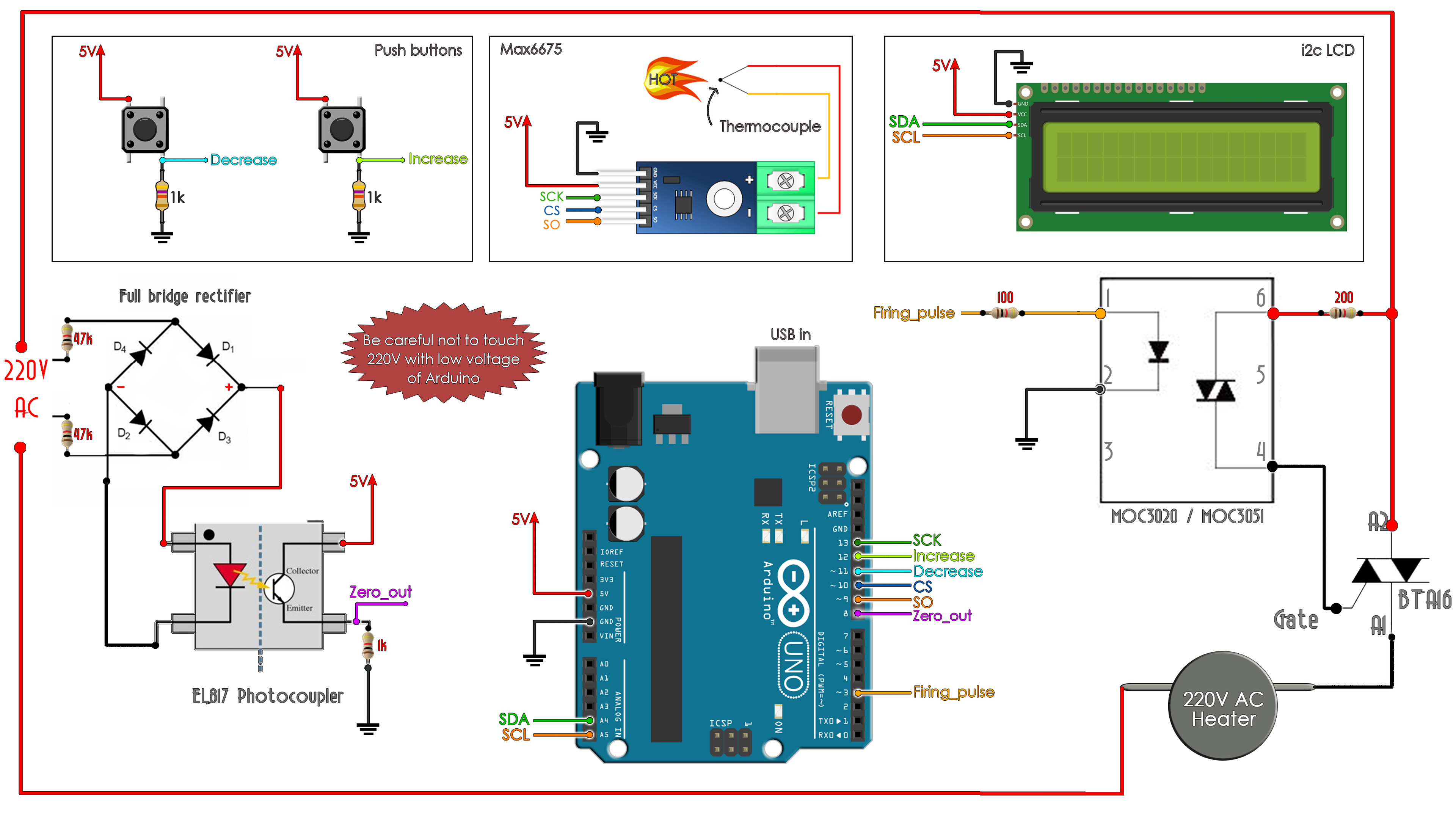
/*    Max6675 Module  ==>   Arduino
 *    CS              ==>     D10
 *    SO              ==>     D9
 *    SCK             ==>     D13
 *    Vcc             ==>     Vcc (5v)
 *    Gnd             ==>     Gnd      */

//LCD config
#include "max6675.h"
#include <Wire.h>
#include <LiquidCrystal_I2C.h>
LiquidCrystal_I2C lcd(0x27,20,4);  //sometimes the adress is not 0x27. Change to 0x3f if it dosn't work.

/*    i2c LCD Module  ==>   Arduino
 *    SCL             ==>     A5
 *    SDA             ==>     A4
 *    Vcc             ==>     Vcc (5v)
 *    Gnd             ==>     Gnd      */

//Inputs and outputs
int firing_pin = 3;
int increase_pin = 11;
int decrease_pin = 12;
int zero_cross = 8;
int thermoDO = 9;
int thermoCS = 10;
int thermoCLK = 13;

//Start a MAX6675 communication with the selected pins
MAX6675 thermocouple(thermoCLK, thermoCS, thermoDO);


//Variables
int last_CH1_state = 0;
bool zero_cross_detected = false;
int firing_delay = 7400;

//////////////////////////////////////////////////////
int maximum_firing_delay = 7400;
/*Later in the code you will se that the maximum delay after the zero detection
 * is 7400. Why? Well, we know that the 220V AC voltage has a frequency of around 50-60HZ so
 * the period is between 20ms and 16ms, depending on the country. We control the firing
 * delay each half period so each 10ms or 8 ms. To amke sure we wont pass thsoe 10ms, I've made tests
 * and the 7400us or 7.4ms was a good value. Measure your frequency and chande that value later */
//////////////////////////////////////////////////////

unsigned long previousMillis = 0;
unsigned long currentMillis = 0;
int temp_read_Delay = 500;
int real_temperature = 0;
int setpoint = 100;
bool pressed_1 = false;
bool pressed_2 = false;

//PID variables
float PID_error = 0;
float previous_error = 0;
float elapsedTime, Time, timePrev;
int PID_value = 0;
//PID constants
int kp = 203;   int ki= 7.2;   int kd = 1.04;
int PID_p = 0;    int PID_i = 0;    int PID_d = 0;

void setup() {
  //Define the pins
  pinMode (firing_pin,OUTPUT);
  pinMode (zero_cross,INPUT);
  pinMode (increase_pin,INPUT);
  pinMode (decrease_pin,INPUT);
  PCICR |= (1 << PCIE0);    //enable PCMSK0 scan
  PCMSK0 |= (1 << PCINT0);  //Set pin D8 (zero cross input) trigger an interrupt on state change.
  PCMSK0 |= (1 << PCINT3);  //Set pin D11 (increase button) trigger an interrupt on state change.
  PCMSK0 |= (1 << PCINT4);  //Set pin D12 (decrease button) trigger an interrupt on state change.
  lcd.init();       //Start the LC communication
  lcd.backlight();  //Turn on backlight for LCD
}


void loop() {
  currentMillis = millis();           //Save the value of time before the loop
   /*  We create this if so we will read the temperature and change values each "temp_read_Delay"
    *  value. Change that value above iv you want. The MAX6675 read is slow. Tha will affect the
    *  PID control. I've tried reading the temp each 100ms but it didn't work. With 500ms worked ok.*/
  if(currentMillis - previousMillis >= temp_read_Delay){
    previousMillis += temp_read_Delay;              //Increase the previous time for next loop
    real_temperature = thermocouple.readCelsius();  //get the real temperature in Celsius degrees

    PID_error = setpoint - real_temperature;        //Calculate the pid ERROR

    if(PID_error > 30)                              //integral constant will only affect errors below 30ºC
    {PID_i = 0;}

    PID_p = kp * PID_error;                         //Calculate the P value
    PID_i = PID_i + (ki * PID_error);               //Calculate the I value
    timePrev = Time;                    // the previous time is stored before the actual time read
    Time = millis();                    // actual time read
    elapsedTime = (Time - timePrev) / 1000;
    PID_d = kd*((PID_error - previous_error)/elapsedTime);  //Calculate the D value
    PID_value = PID_p + PID_i + PID_d;                      //Calculate total PID value

    //We define firing delay range between 0 and 7400. Read above why 7400!!!!!!!
    if(PID_value < 0)
    {      PID_value = 0;       }
    if(PID_value > 7400)
    {      PID_value = 7400;    }
    //Printe the values on the LCD
    lcd.clear();
    lcd.setCursor(0,0);
    lcd.print("Set: ");
    lcd.setCursor(5,0);
    lcd.print(setpoint);
    lcd.setCursor(0,1);
    lcd.print("Real temp: ");
    lcd.setCursor(11,1);
    lcd.print(real_temperature);
    previous_error = PID_error; //Remember to store the previous error.
  }

  //If the zero cross interruption was detected we create the 100us firing pulse
  if (zero_cross_detected)
    {
      delayMicroseconds(maximum_firing_delay - PID_value); //This delay controls the power
      digitalWrite(firing_pin,HIGH);
      delayMicroseconds(100);
      digitalWrite(firing_pin,LOW);
      zero_cross_detected = false;
    }
}
//End of void loop
// |
// |
// |
// v
//See the interruption vector


//This is the interruption routine (pind D8(zero cross), D11(increase) and D12(decrease))
//----------------------------------------------

ISR(PCINT0_vect){
  ///////////////////////////////////////Input from optocoupler
  if(PINB & B00000001){            //We make an AND with the state register, We verify if pin D8 is HIGH???
    if(last_CH1_state == 0){       //If the last state was 0, then we have a state change...
      zero_cross_detected = true;  //We have detected a state change! We need both falling and rising edges
    }
  }
  else if(last_CH1_state == 1){    //If pin 8 is LOW and the last state was HIGH then we have a state change
    zero_cross_detected = true;    //We haev detected a state change!  We need both falling and rising edges.
    last_CH1_state = 0;            //Store the current state into the last state for the next loop
    }

    if(PINB & B00001000){          //We make an AND with the state register, We verify if pin D11 is HIGH???
      if (!pressed_1)
      {
        setpoint = setpoint + 5;   //Increase the temperature by 5. Change this with your value if you want.
        delay(20);
        pressed_1 = true;
      }
    }
    else if (pressed_1)
    {
      pressed_1 = false;
    }

    if(PINB & B00010000){          //We make an AND with the state register, We verify if pin D12 is HIGH???
      if (!pressed_2)
      {
        setpoint = setpoint - 5;   //Decrease the temperature by 5. Change this with your value if you want.
        delay(20);
        pressed_2 = true;
      }
    }
    else if (pressed_2)
    {
      pressed_2 = false;
    }
}
//End of interruption vector for pins on port B: D8-D13


