


This setup is an AC 220 volts PID control for temperature. In previous tutorials, if you remember, we have made a PID temperature control for DC voltage and a TRIAC AC voltage control. A lot of you asked me for a combination between those two videos. So, today we will read the temperature with a thermocouple, detect the zero cross of the AC voltage, create the PID control and change the firing angle at the TRIAC gate and by that control the temperature of a 220V heater.
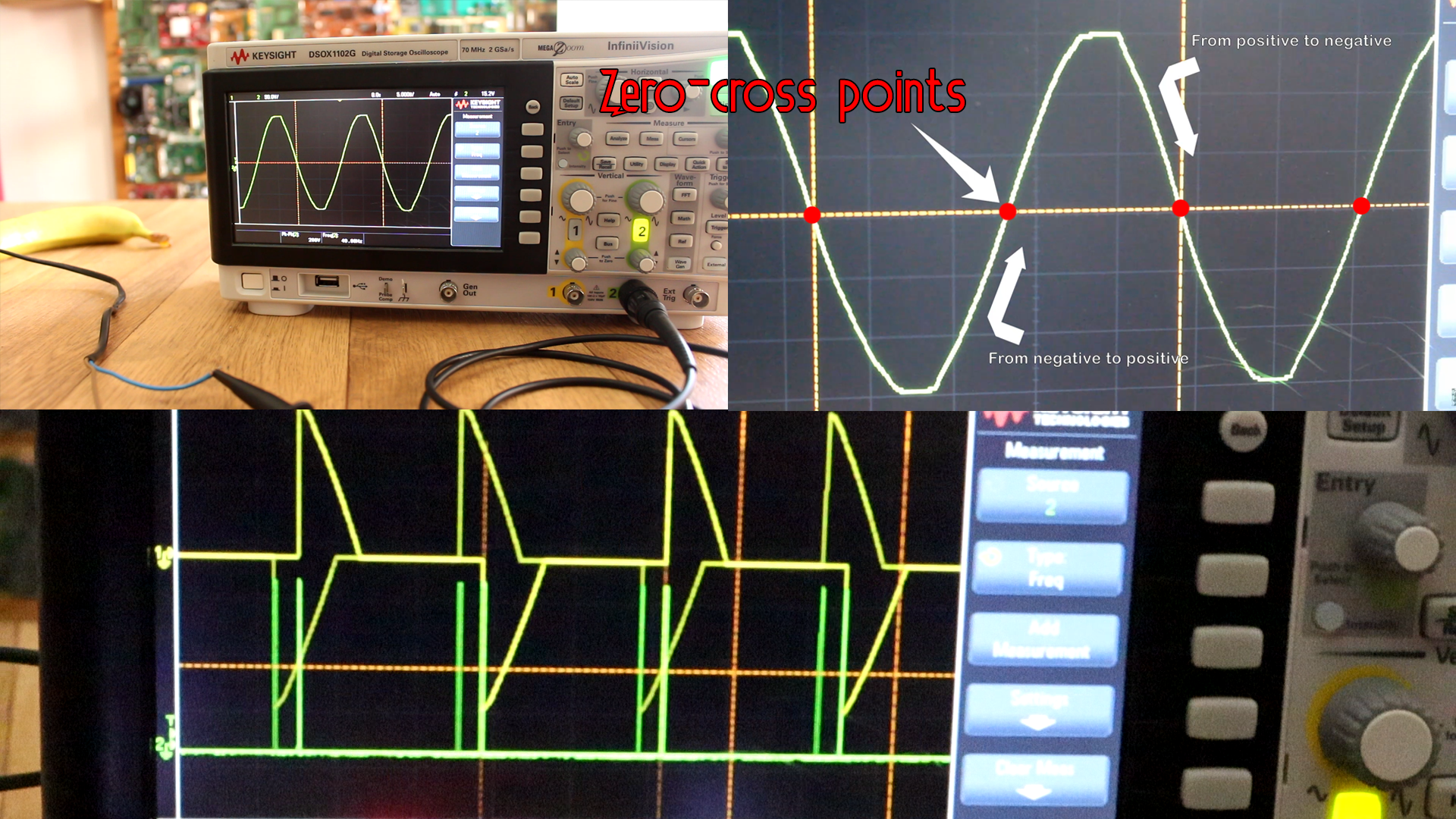
Ok, below you can see the 220V sine wave. As you can see it passes the same amount of time below 0V as above 0V. We need to detect the moment when the wave passes from negative to positive or vice-versa. Why? Well, after the zero-cross, if we send a firing pulse to the TRIAC, we could control the amount of the wave will pas and by that the amount of power as we will se later. So in order to be synchronized, we need to detect the zero-corss.
So, witha microcontroller we need to detect that zero-cross. How we do that? well we use two components and those are a full-bridge rectifier and an photocoupler. We do that because the microcontroller can't work with negative voltages and above 5V. The full-bridge rectifier will give only positive wave and the photocoupler will lower the voltage to 5Vpp. Now we could read that signal with an Arduino. See the signal below.
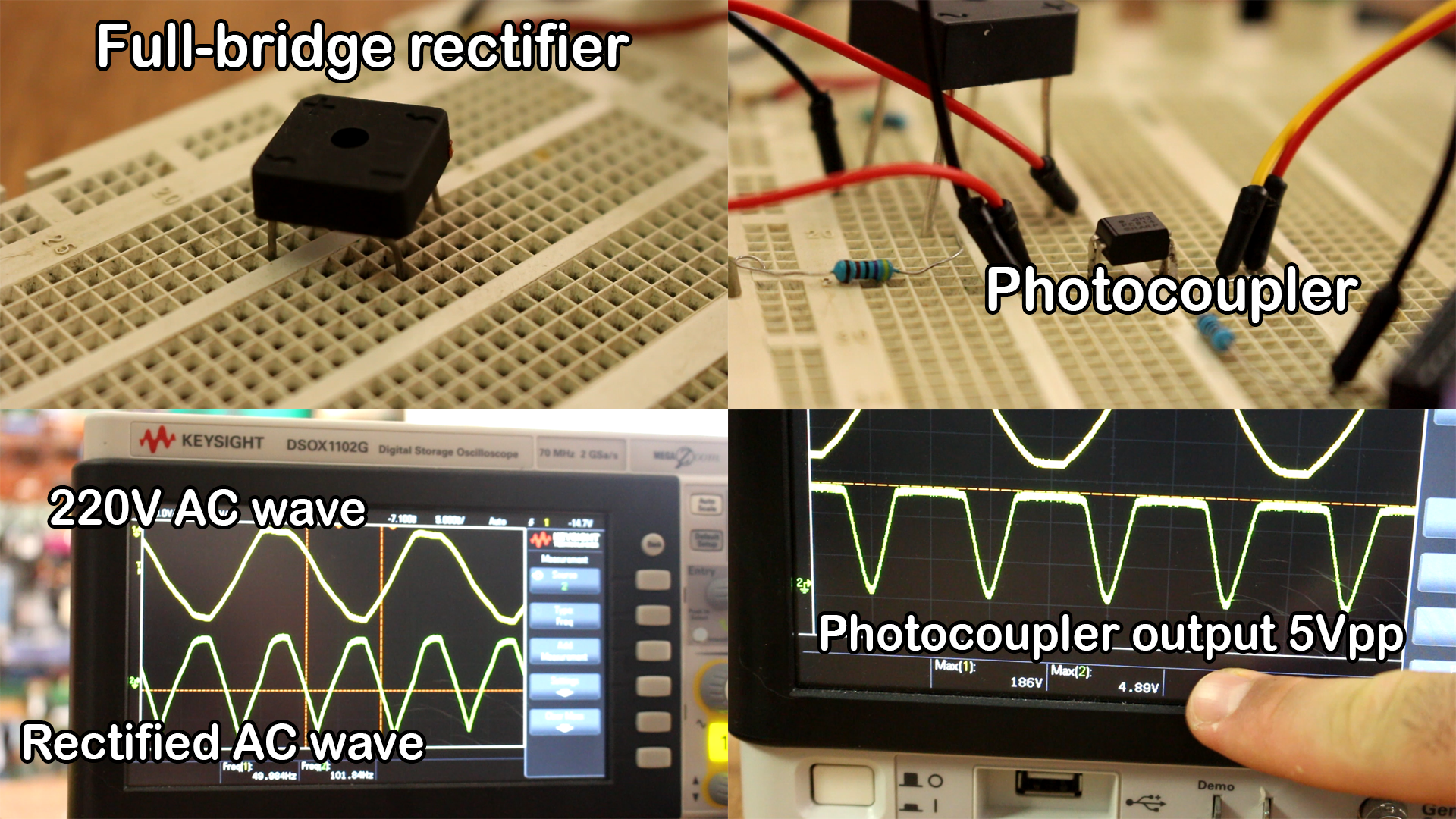
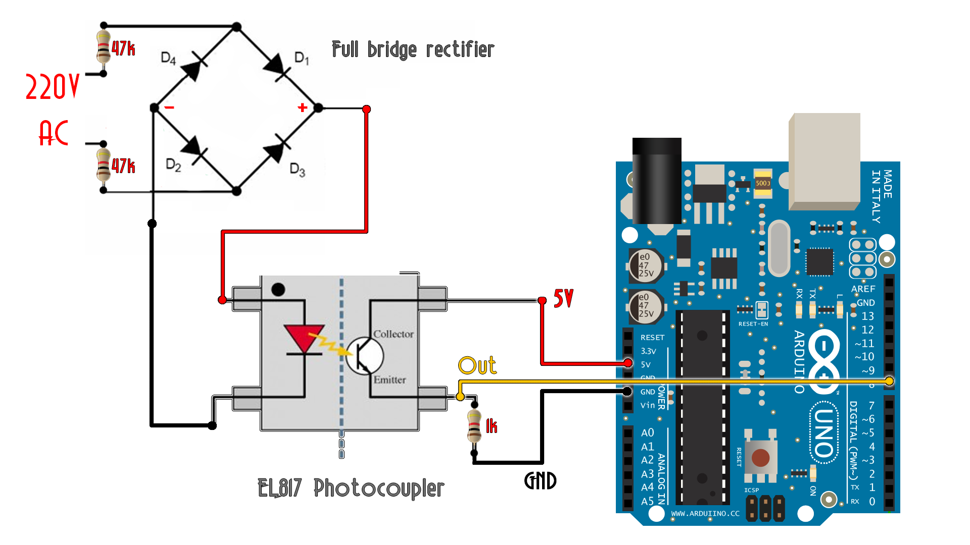
As you can see in the photo above on the 5Vpp signal, we have a los pulse each zero cros now. With the Arduino is very easy to detect that. We will see later in the code, an interruption made on digital pin D8. To read that pulse, the next scheamtic was used for the full-bridge rectifier and the photocoupler.
How to read the thermocouple with the amplifier mdoule and the Arduino. make the connections as below.
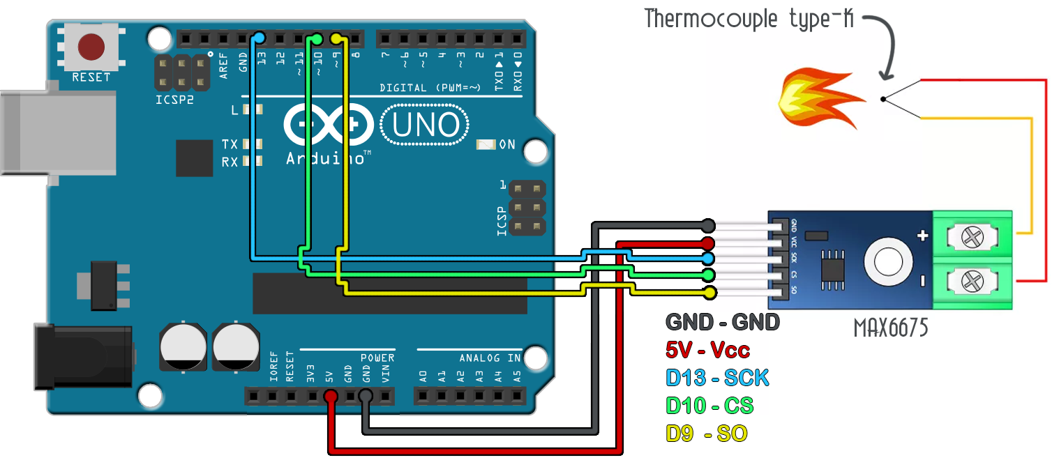
Ok, see the scheamtic above. Connect the K-type Thermocouple as shown and connect the the SPI pins to D13, D10 and D9. To test the circuit, upload the enxt example code and open the serial monitor at a baud rate of 9600. Heat the thermocouple and see the resuls.
#include "max6675.h"	//INCLUDE THE LIBRARY

int thermoDO = 9;
int thermoCS = 10;
int thermoCLK = 13;

MAX6675 thermocouple(thermoCLK, thermoCS, thermoDO);

void setup() {
  Serial.begin(9600);
  Serial.println("MAX6675 test");
  // wait for MAX chip to stabilize
  delay(500);
}

void loop() {
  // basic readout test, just print the current temp
   Serial.print("C = ");
   Serial.println(thermocouple.readCelsius());
   Serial.print("F = ");
   Serial.println(thermocouple.readFahrenheit());
   delay(1000);
}
Ok, now we know how to measure temperature with the K-type thermocouple. Now we have to see how to control the power applied to the AC heater using the TRIAC.
Ok, see more about TRIAC control on the past tutorial here. Below you have the final schematic for this project. We have the rectifier and photocoupler to detect the zero-cross, then the thermocouple to read the temperature and finally the TRIAC connected to the 220V AC heater. Also some buttons and an LCD in order to print the setpoint and real temperature.
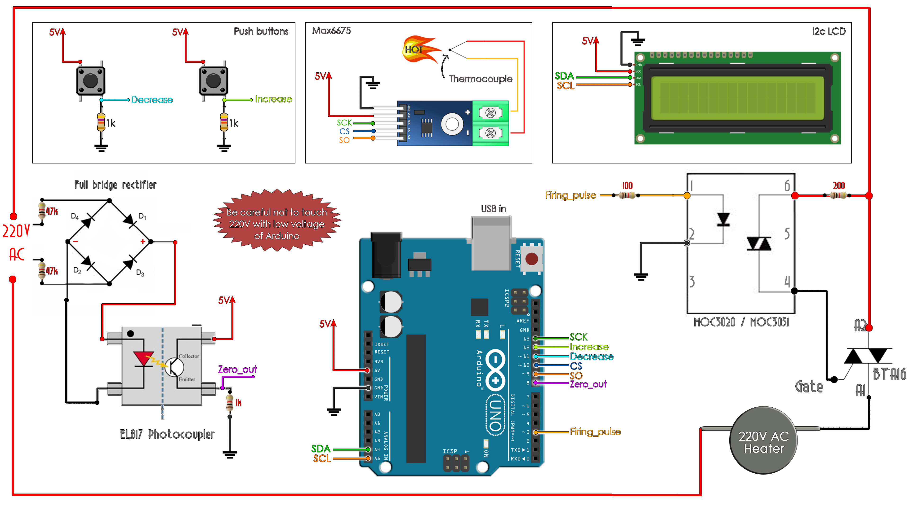
We detect the zero-cross, measure the temperature, calculate the delay of the firing pulse with the PID control and create the pulse on the "Firing_pulse" fin connected to the MOC3020 optocoupler that will apply a pulse to the TRIAC. This will control the amount of power that will pass to the AC heater as you can see in the photo below.
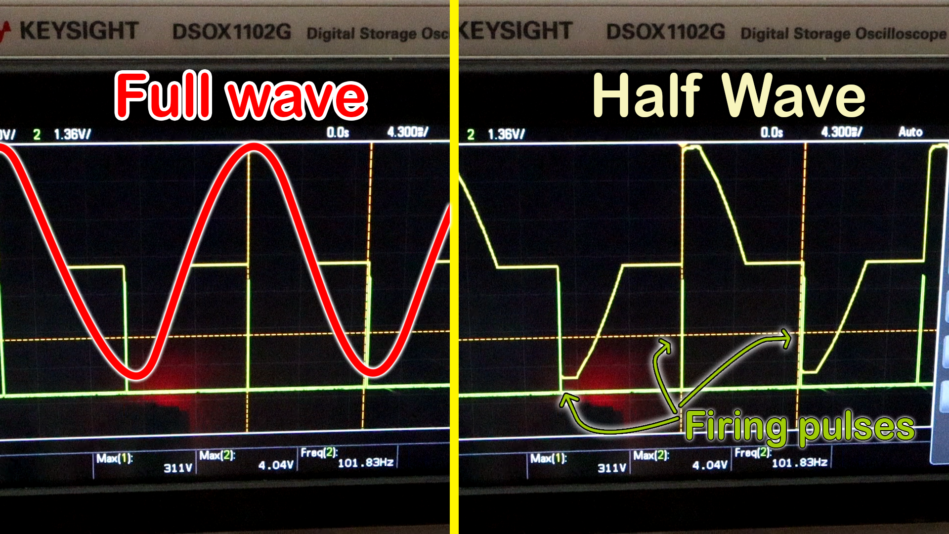
The small bit of code below is the one taht creates the small firing pulse of 100us. With the delayMicroseconds(maximum_firing_delay - PID_value); we control the delay between the zero-cross and the firing pulse and by that the amount of the wave that will pass. In the photo below the amout of wave is more or less 50%.
  //If the zero cross interruption was detected we create the 100us firing pulse
  if (zero_cross_detected)
    {
      delayMicroseconds(maximum_firing_delay - PID_value); //This delay controls the power
      digitalWrite(firing_pin,HIGH);
      delayMicroseconds(100);
      digitalWrite(firing_pin,LOW);
      zero_cross_detected = false;
    }


