@tutorial:
ELECTRONooBINO - Make your own Arduino UNO
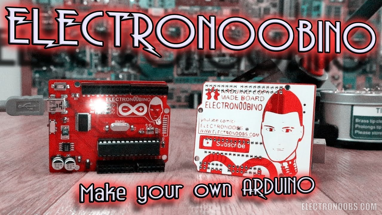
This is my electronubino, version 1. O. In this tutorial I will show you how I’ve made my own board as the Arduino Uno but with some unique addons that I wanted. My board has double row of pins, SPI port compatible with this NRF24 modules because I use those a lot, mini B USB port, white LEDs and some unique logos. So, let’s get started.
by: ELECTRONOOBS on 2026-07-24
1 x ATMega328p- PU LINK eBay
1 x ATMega328p- PU SOCKET LINK eBay
1 x FT232RLSSOP LINK eBay
OR: 1 x CH340 LINK eBay
1 x AMS1117-5.0V LINK eBay
OR: 1 x MC33269DR2-5 LINK eBay
1 x 16MHz crystal LINK eBay
1 x MINI-B USB conn LINK eBay
1 x smd push button LINK eBay
4 x female pins LINK eBay
1 x M7 diode LINK eBay
1 x 500mA fuse LINK eBay
1 x smd switch LINK eBay
3 x 0805 LEDs LINK eBay
5 x 0805 1k resistor LINK eBay
1 x 0805 10k resistor LINK eBay
2 x 0805 22pF capacitor LINK eBay
3 x 0805 100nF capacitor LINK eBay
2 x 47uF SMD capacitor LINK eBay
1 x 0805 1uF capacitor LINK eBay
Wire, soldering iron, solder, etc...
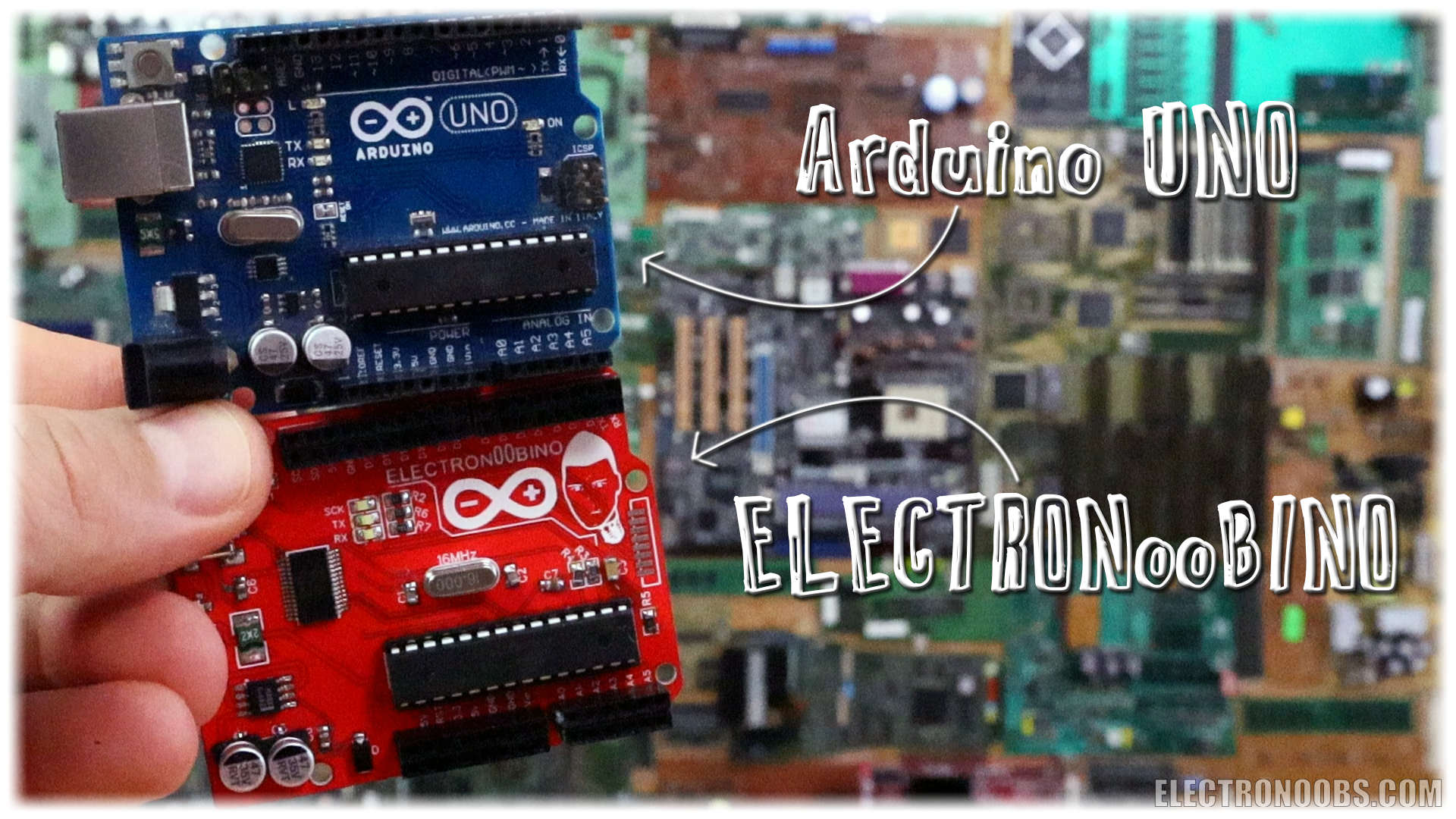
If you’ve been on this website for a while, I bet you know what the Arduino microcontroller is. There are many versions of Arduino using the Atmega328 chip. There is the Arduino UNO, the NANO, the pro mini and other versions of boards that use the same chip.
For tests, when I’m building a new project, I almost always use the Arduino UNO because it is simple, it has female pins for me to connect jump wires, it has a USB connector to program it, has external supply plug and voltages of 5 and 3,3 volts.
In this project, I’ve made my own unique Arduino UNO and name it ELECTRONOOBINO, and I’ll show you how to make your own. You, see, Arduino is an open hardware development board, all the components are free to buy and use, so, I could gather all the components and make my own board and call it whatever I want. Before we start, I want to thank to the Arduino community for all they’ve done. Without Arduino, my channel/webpage would probably not even exist, it basically changed my life.
So, why I’m showing you this? Well, once you know how to make the Arduino schematic, you could build your own boards with the ATmega microcontroller as I’ve made with my drone board, the radio controller, this portable soldering iron and my CNC machine.
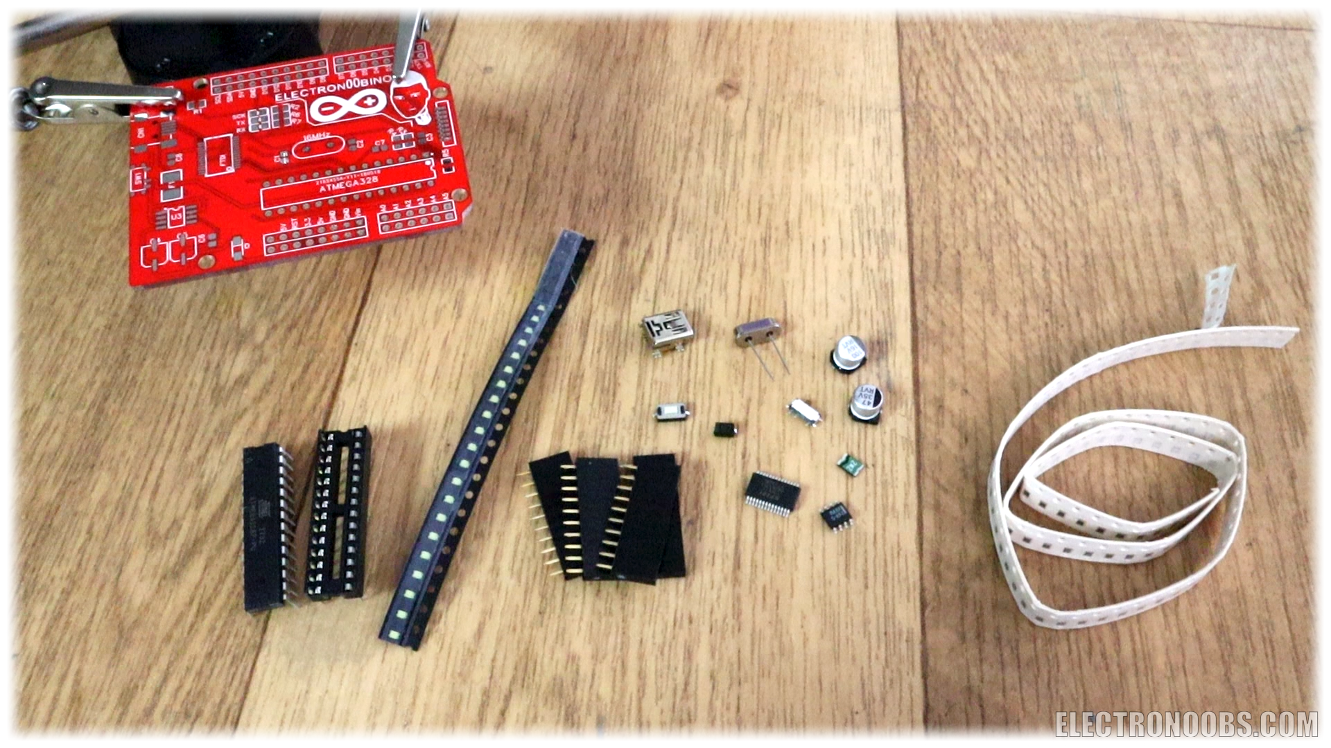
First of all, below you have a full part list for my design. If you make your own using other components, make sure you use good adn low cost components. There are different options for the voltage regulator, FTDI communication adn so on...
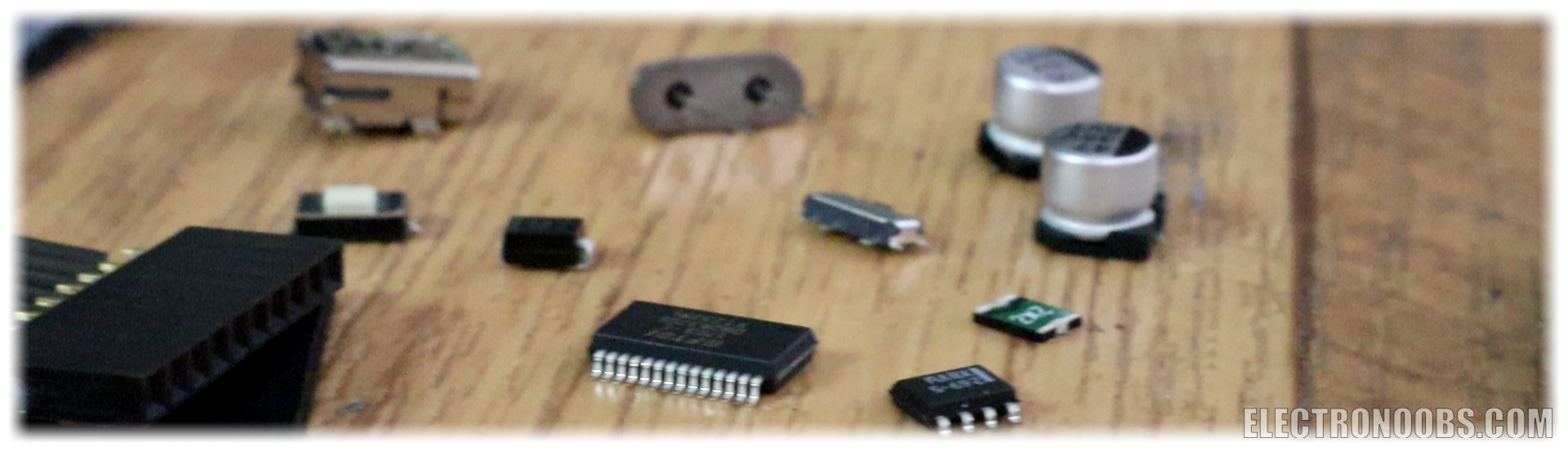
Ok, so first let’s decide what components we need? We must have the ATMega328-p microcontroller. We could have that in an AU or PU format. I’ll use PU format with a socket since I might want to remove the chip sometime.
Ok, the microcontroller can’t work by itself. It needs the bare minimum configuration in order to work. This is all it needs to work.
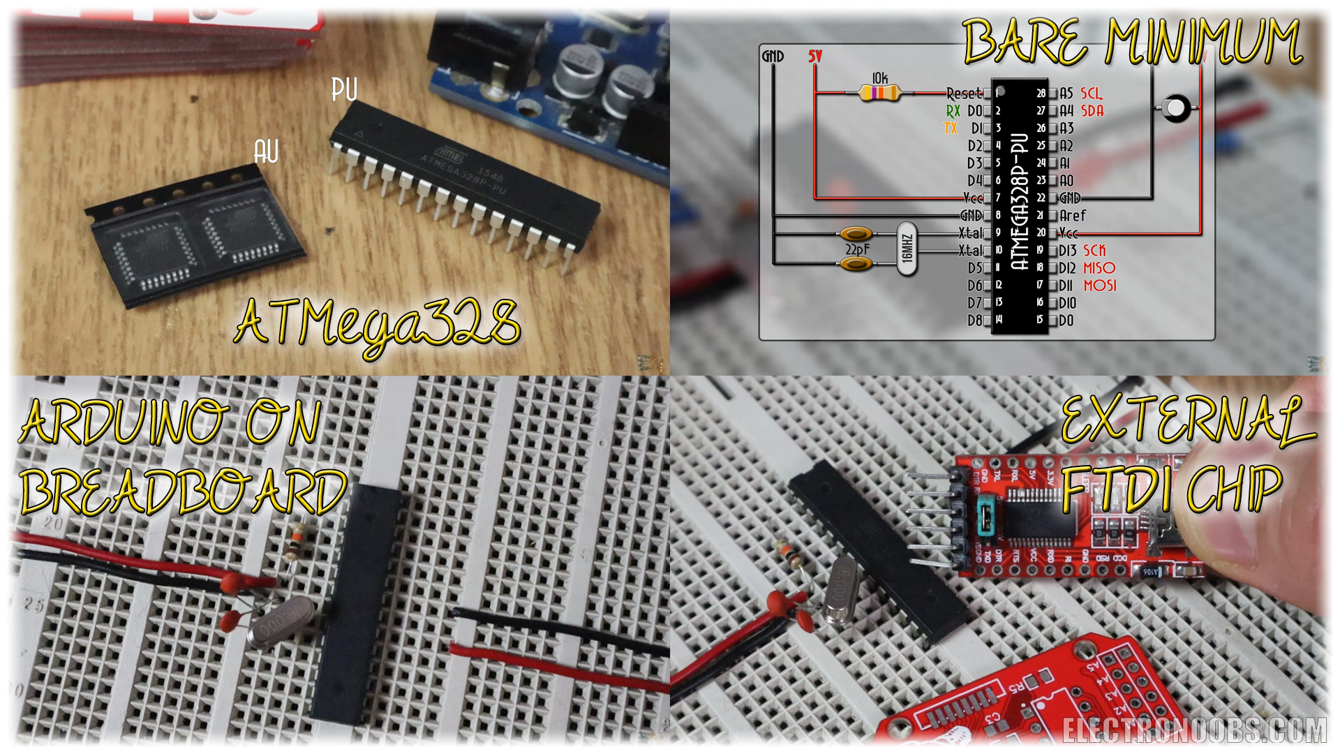
Now we haev the bare minimum config on the breadboard and tested. If you were able to uplaod code to it using the FTDI module, great. We can start with the project. Once this configuration works, you could make any board that you want.
Ok, now that we know the bare minimum configuration, let’s analyze the extra components the Arduino UNO has. First of all, as said before, I had to use and external FTDI chip to program the Arduino. My board will have that included. This chip makes the connection between the USB data and the ATMEGA328 so we could upload our sketches to the microcontroller. We also need a 5V voltage regulator, the USB plug, a reset push button, female pins all around, some extra capacitors, LEDs and a switch.
This is the schematic for my board. Let me explain the options for these different components. For the UART communication between the ATMEGA chip and the USB you could use the FT232RL chip as I did for this board, but also the CH340 chip. Check the schematic for each configuration below.
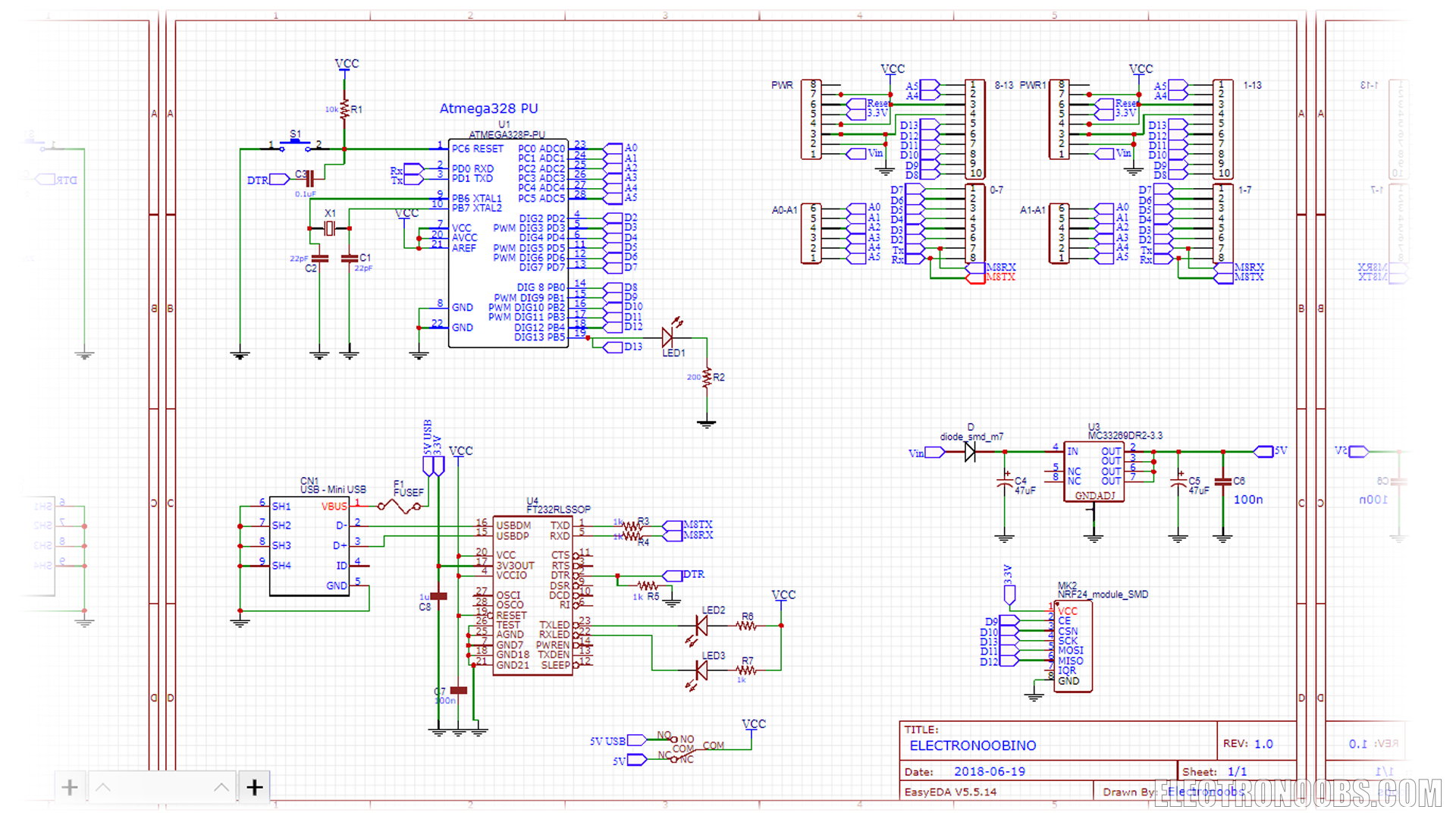
I’ve used EASYEDA to create my schematic and layout. Go to EASYEADA.com and create a new project and give it a name. Now this will open a new schematic sheet. We can start adding components. Before you start, you should have a list with the components that you need.
Go to libraries and start searching for the selected components. I add the ATMEGA328 DIP version, I place the FT232 communication chip, the voltage regulator, the USB connector and the pin connectors. I have the pins two times, since I want two lines of pins.
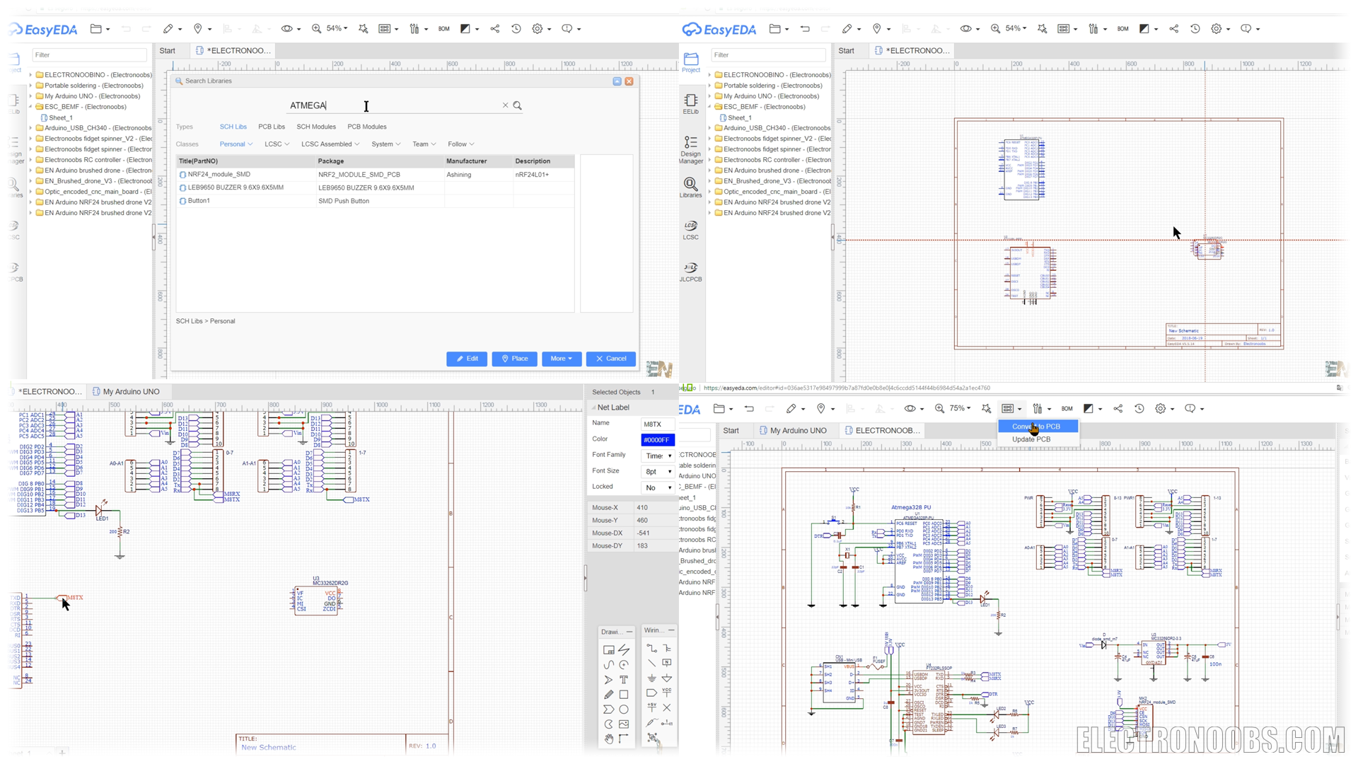
Now to make connections, you could use directly the wire but that would live your schematic a mess. Instead use the net port label. Add this net por and give it a name. Now go to the other port and add the same label with the same name. Now, those two points are connected. Remember, the label name has to be the same. I’ve placed all the extra components such as resistors, capacitors and a fuse here at the USB power input. In my case all SMD capacitors, resistors and LEDs are 0805 size so they are not that difficult to be soldered later.
Ok, this was my final schematic. Always check the price of each component before you start creating the layout because there could always be a cheaper component that you could use.
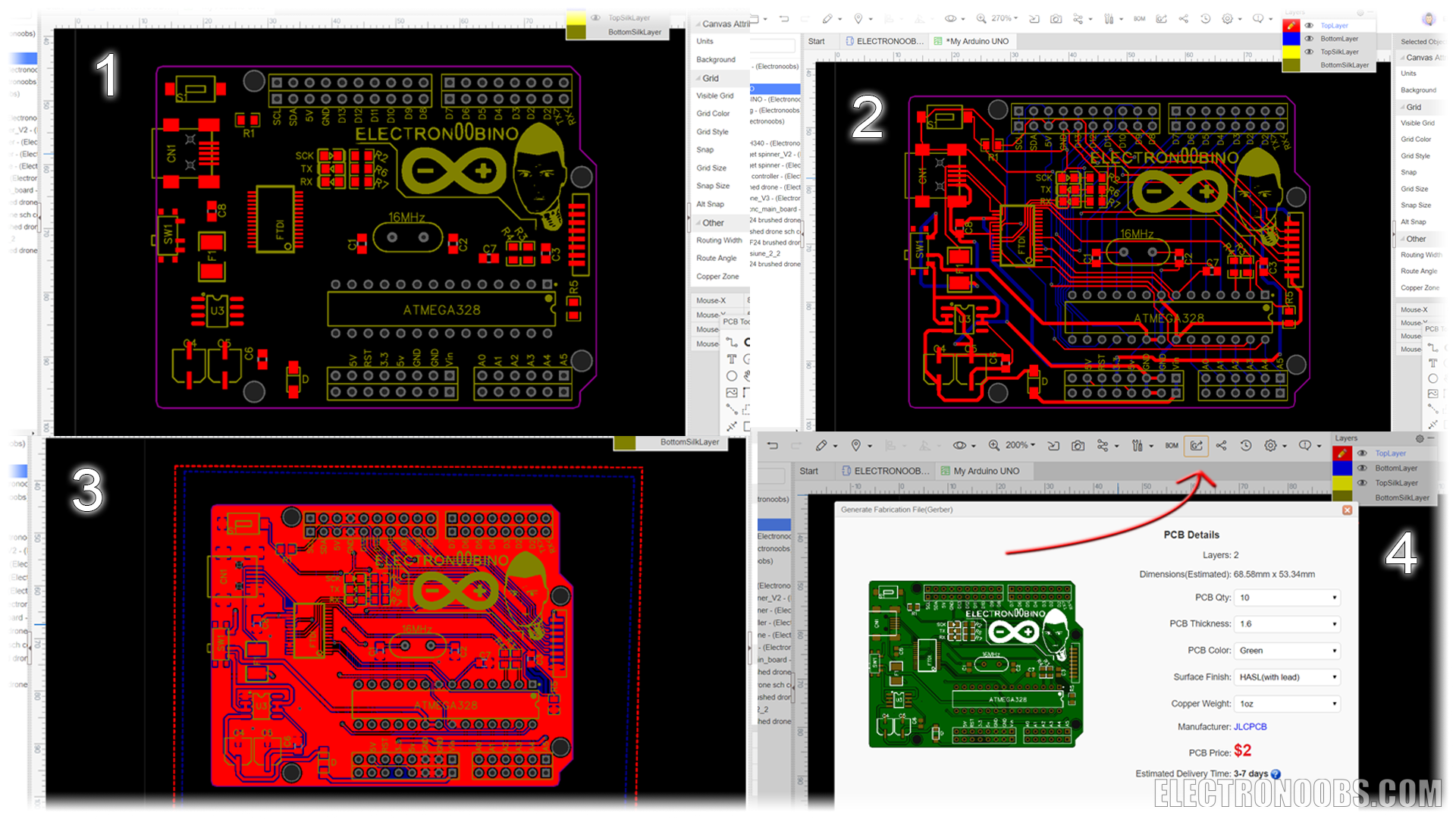
Once the schematic is done and you are sure there are no errors, click convert to PCB button in top panel of easyEDA. Now here we haev our board and all the components around. Here is what I’ve done: Go to libraries and search for Arduino UNO. Somebody already made the shape of the UNO board. Place that shape on your layout and start giving your board the same shape. The board outline is marked by the pink line. Once the shape is the same as the Arduino UNO, place 4 vias of 3.5mm diameter and a hole of 3mm in the same place as the Arduino board holes. Place the female pins in the same position and once that is done, you could delete the Arduino board.
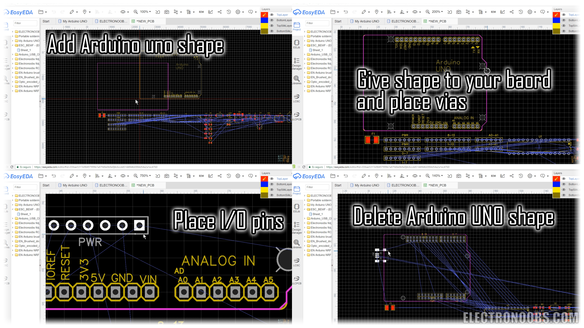
Now I place my components in the position that I want. The USB connector on one side, the FTDI chip between the USB and the ATMEGA328, the voltage regulator with some capacitors on left low side, the fuse, the power switch, the reset button, the LEDs and here the SPI port just in case I want to add the NRF24 spi module.
Ok, is time to route all the tracks. I really prefer do this manually but you could also use the autoroute option. Also, make the power lines a bit thicker. My power lines are of 0.6mm and signals of 0.25mm. Make sure you don’t have many squared angles for the signal tracks and that the decoupling capacitors are close enough to the chip. So, this is my layout. Finally, I add a copper area for both layers and save the file.
Ok, now we haev the gerbers in .zip file. I select order at JLCPCB. A new page will open and here I can see my board. Click view gerber and inspect it one more time. Select your settings. I’ve selected red color, 10 boards and 2 layers. For red color the price is of 9 euros, but for green you will pay the amazing price of only 1.62 euros.
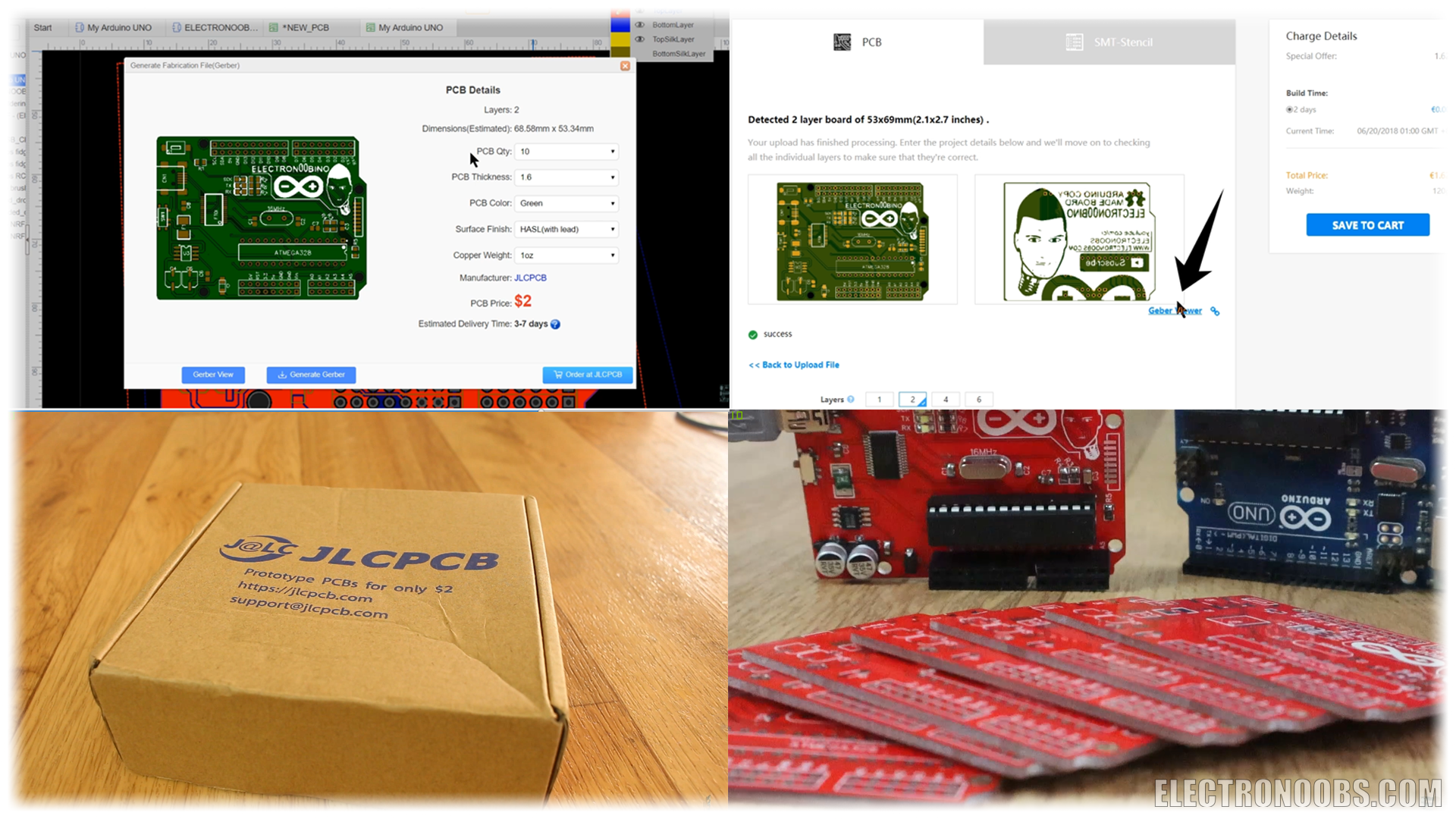
Ok, save to cart. For Spain, as you can see I’ve paid only 6 more dollars for shipping. Time is not a problem for me so I never use DHL because it is very expensive. Pay the boards and wait for the order to arrive. With DHL you would receive the boards to Spain in around 5 days which is amazing, but, with normal shipping in 2 weeks which is not that bad. For new customers JLCPCB has free shipping during this time of year. SO, ordering the green color, 10 PCB of 10 by 10 cm and 2 layers, you will only pay 2 dollars.
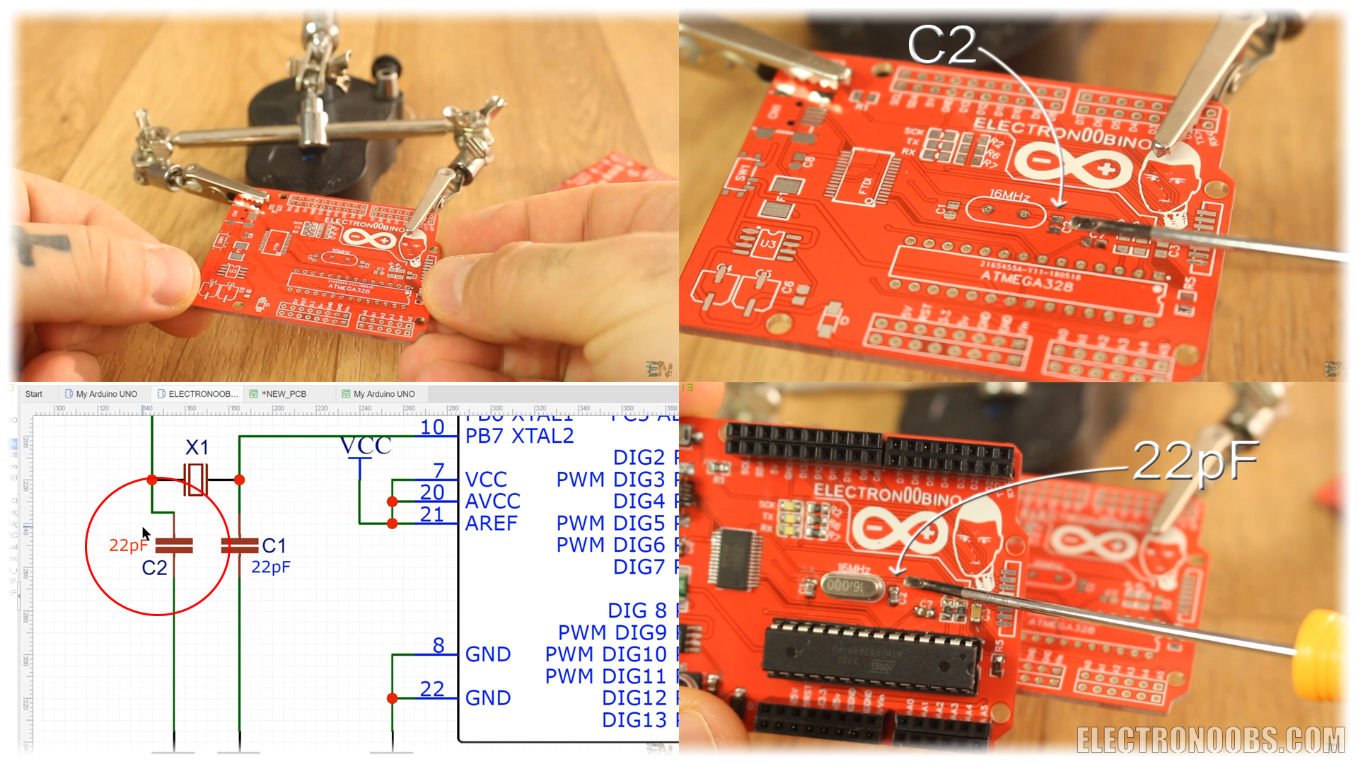
Ok, I’ve received my boards. Now, with the schematic on the side I start soldering the components. The board has silk layer so I can see the name of each components.
Now, with the schematic on the side I start soldering the components. The board has silk layer so I can see the name of each components. . For example, inj the photo below we have C2 capacitor. I go to the schematic and see its value. I get that value and solder it to my PCB. Do that for each component.
Now everything is soldered in place. Is time to add the ATMEGA chip. Be careful and not put it backwards. Check pin one marked with this dot here on the corner. We have the same dot on the silk layer of the bopard. Now, if the chip doesn’t have a bootloader burned to it you should burn it first.
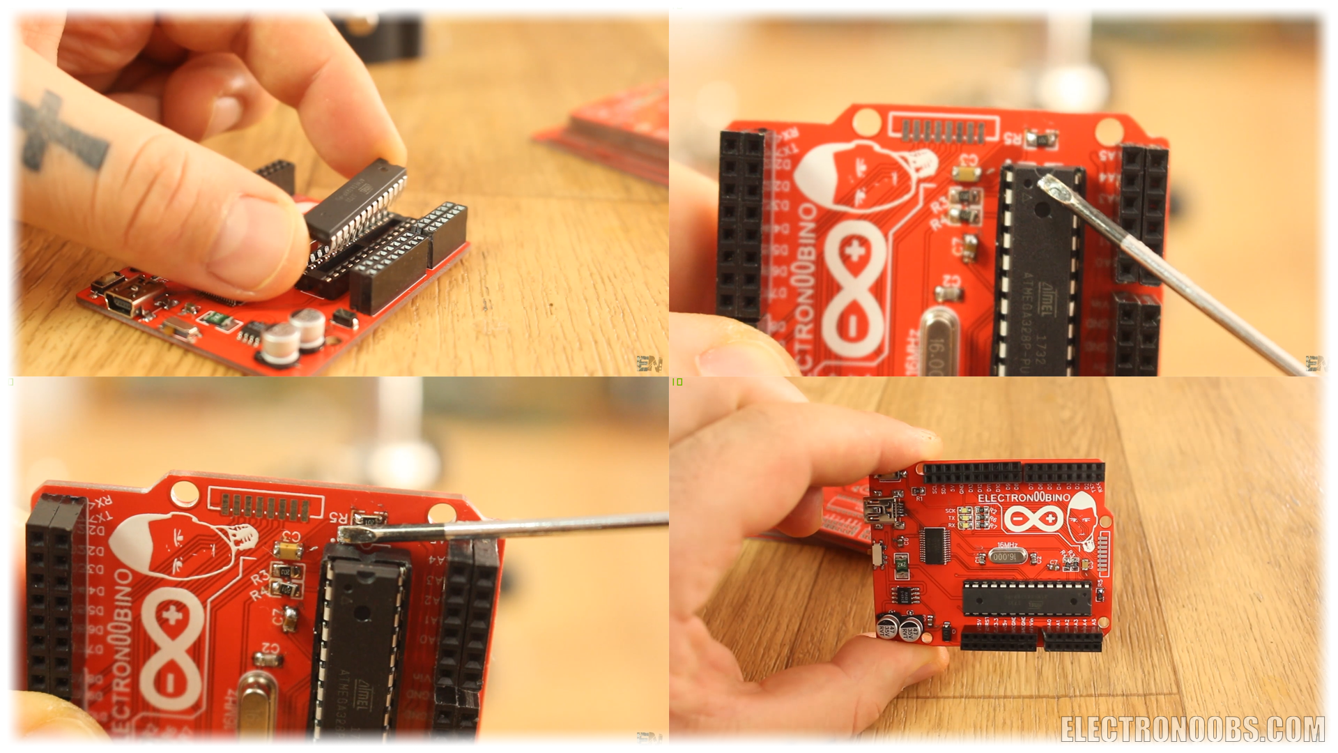
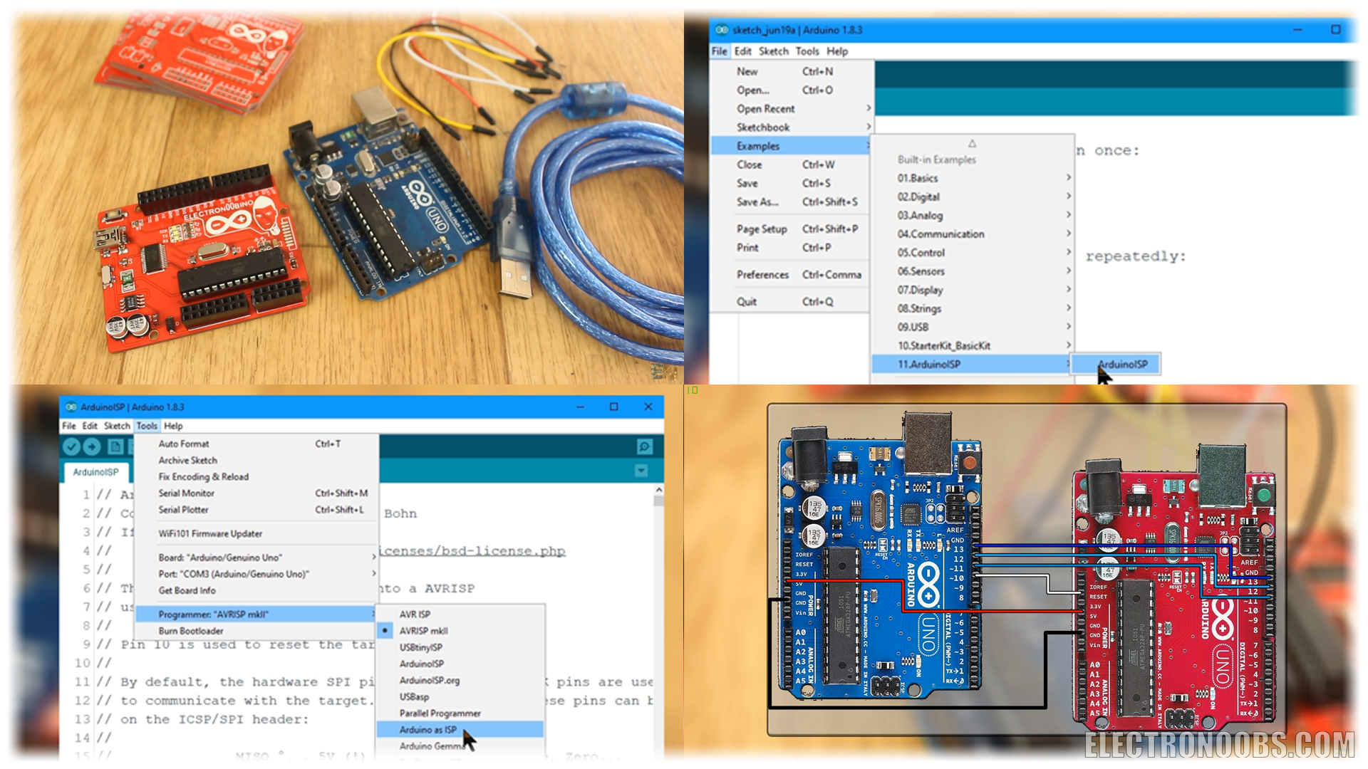
Now, if the chip doesn’t have a bootloader burned to it you should burn it first. Here is what you need to burn a bootloader to a new ATMEGA chip:
- Another Arduino UNO
- Some jump cables and
- USB cable
Connect the Arduino UNO to your PC and open ARDUINO IDE. Select Arduino board and go to examples ? Arduino ISP ? and open this example. Now upload this file to the Arduino UNO (original one). Now go to tools and change the programmer to Arduino as ISP.
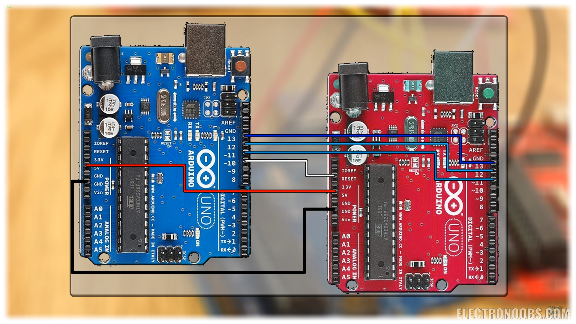
Now make these SPI connections between the stock Arduino and your board. Once the connections are made, go to tools and select burn bootloader. The LEDs will start blinking very fast. Once you get the message bootloader successfully burned you are good to go.
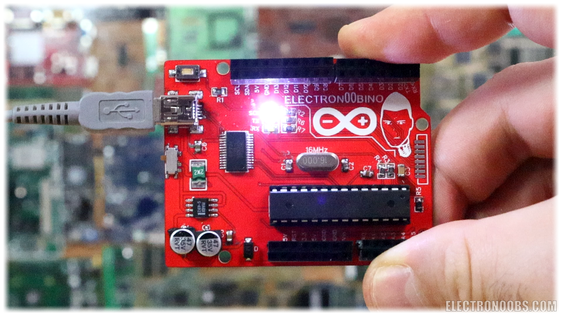
Connect the USB to your board, change back the programmer mode and upload a test sketch. There you go, I’ve made the LED blink with my ELECTRONOOBINO board. Pretty cool right?
This board works exactly like the Arduino UNO, but it is made just how I wanted. More female pins, SPI pads here and great color. You can find all the extra information, schematics, gerbers and photos in this tutorial. So there you have it guys. This is my ELECTRONOOBINB board. Tell me what do you think about it, if you will build one yourself or if you like my design.
I hope that you’ve enjoyed this tutorial/project. If so don’t forget to check my Youtube channel. If you have any question about this project or any other, just leave it in the comment section below or on my forum page. Also, don’t forget to subscribe and watch all of my other great tutorials. Remember, if you consider helping my projects check my Patreon page as well.
Thanks again and till next project.
Comments

Leave a comment
Please login in order to comment.