
Get the code from below. You will also need some libraries for the OLED display and the ADC1115 Ic. make sure you download those as well from teh link below and install them to the Arduino IDE. Then connect the FDTI programmer to those UART pads. DTR to DTR, RX to TX, TX to RX, GND and Vcc and upload the code. The code is quite long but you have comments that should help you understand. See the schematic at the same time in order to understand better.
/////////////////////////////Library for ADS1115 ADC//////////////////////////////////
#include <Adafruit_ADS1015.h>       //download here: https://www.electronoobs.com/eng_arduino_Adafruit_ADS1015.php
Adafruit_ADS1115 ads(0x48);
//////////////////////////////////////////////////////////////////////////////////////

////////////////////////OLED 64x124 display with i2c//////////////////////////////////
//OLED screen libraries
#include <Adafruit_GFX.h>           //download here: https://www.electronoobs.com/eng_arduino_Adafruit_GFX.php
#include <Adafruit_SSD1306.h>
#define OLED_RESET 11
Adafruit_SSD1306 display(OLED_RESET);
//////////////////////////////////////////////////////////////////////////////////////
Go below and downlaod the STL files for the case. It has only 2 main parts and 4 smaller parts. The small parts are 2 push buttons and 2 sliding swithces. We use those to control the buttons and switches on the PCB. I've printed itr with PETG with 2 perimeters, 20% infill, 0.3 layer height and a 0.4mm nozzle.
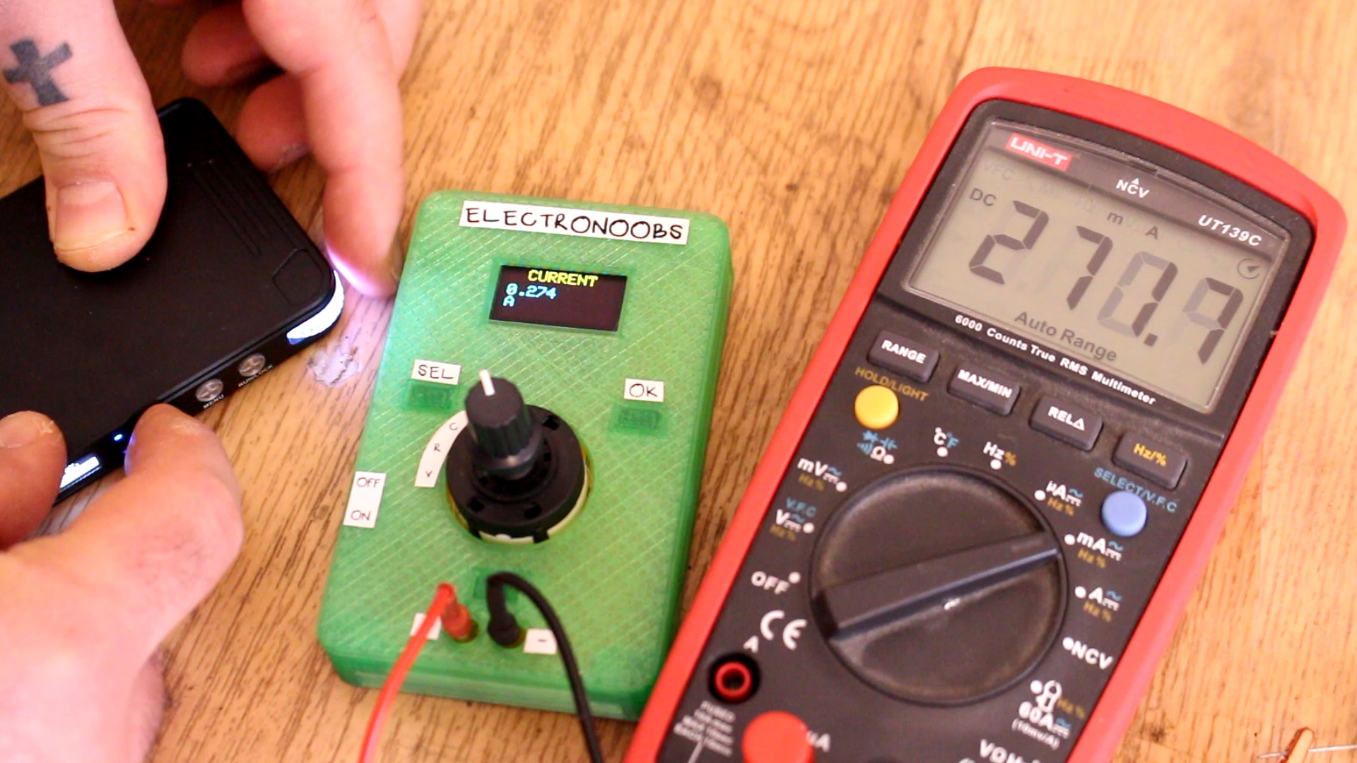
Rotate the switch and test each mode. You might need to adjust some variables in the code. Test the values with a commercial multimeter as well in order to compare. When you get good results, place the PCB isnide the case and that's it. The project is done.
