Well, you could just go to eBay and buy a kit like this one with everything ready for assemble. But that is not as fun as making one. In this tutorial I show you how I've made my own acrylic display with RGB LEDs and adressable LED strip, so we could place multiple displays in series. By engraving a different shape, you could show any other shape. In this case I've used G-code and my CNC mill and engraved numbers from 0 to 9.
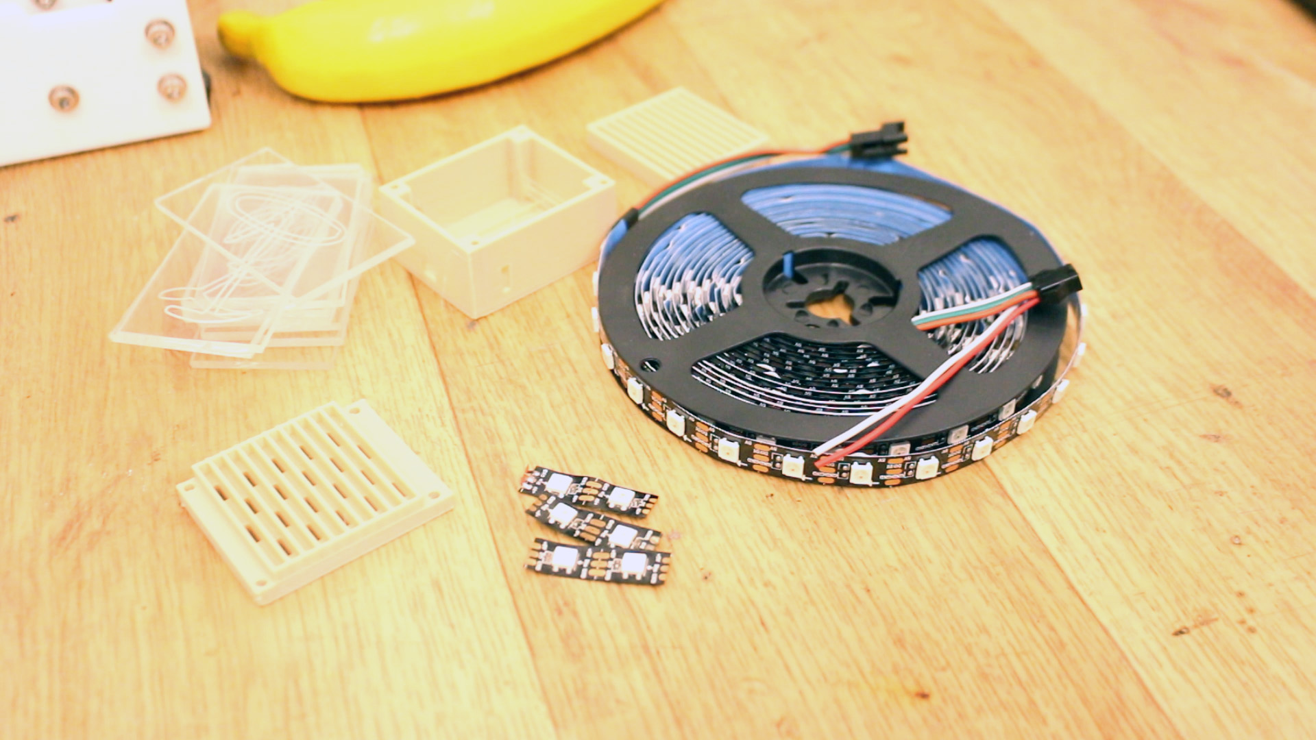
Part list is very short. We need the 2mm Acrylic boards. These are 20 by 30 cm. So, if we divide 20cm into pieces of 4cm wide, we can get 5 for each 7cm row. We can get 4 rows, so a totral of 20 4x7cm boards with each 20x30cm board. We need the PCB I've made or just solder the LEDs like I've did for my homemade version. Then we need 20 WS2812 LEDs for each display. Also some thin wires and an Arduino NANO.
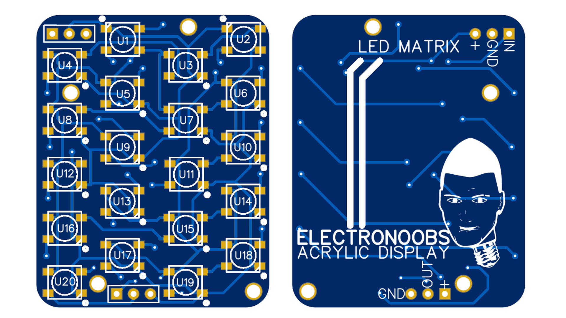
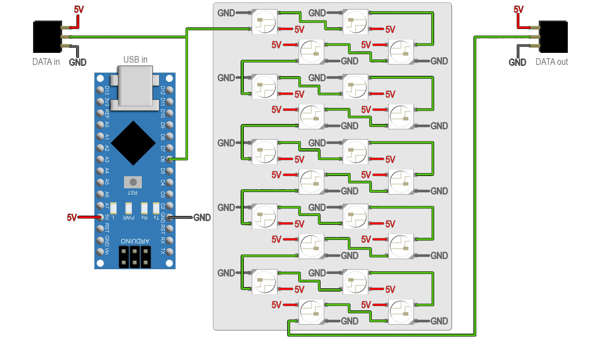
This is the scheamtic in case that you solder the LEDs directly on a prototyping PCB like I did. As you can see each LED has a mark on the corner adn that will show you GND pin. Connect GND and Vcc to each LED and then the serial wire from the Arduino to the first LED, from that LED to the next and so on in zig zag. Also connect the wires for 5V, GND and signal to the female pins for input adn output for each display. For the PCB you can download below, the schematic is the same. We have just LEDs and nothing more.
Go below and dowloand the GERBER for the PCB and order it to JLCPCB for example. Then you can solder all the LEDs. Again, the mark on the corner of the LED marks the GND pin. Is quite impossible to place it backwards. Then solder wires at the input and output. The PCB has 3mm holes in case you want to screw it in place to your own case.
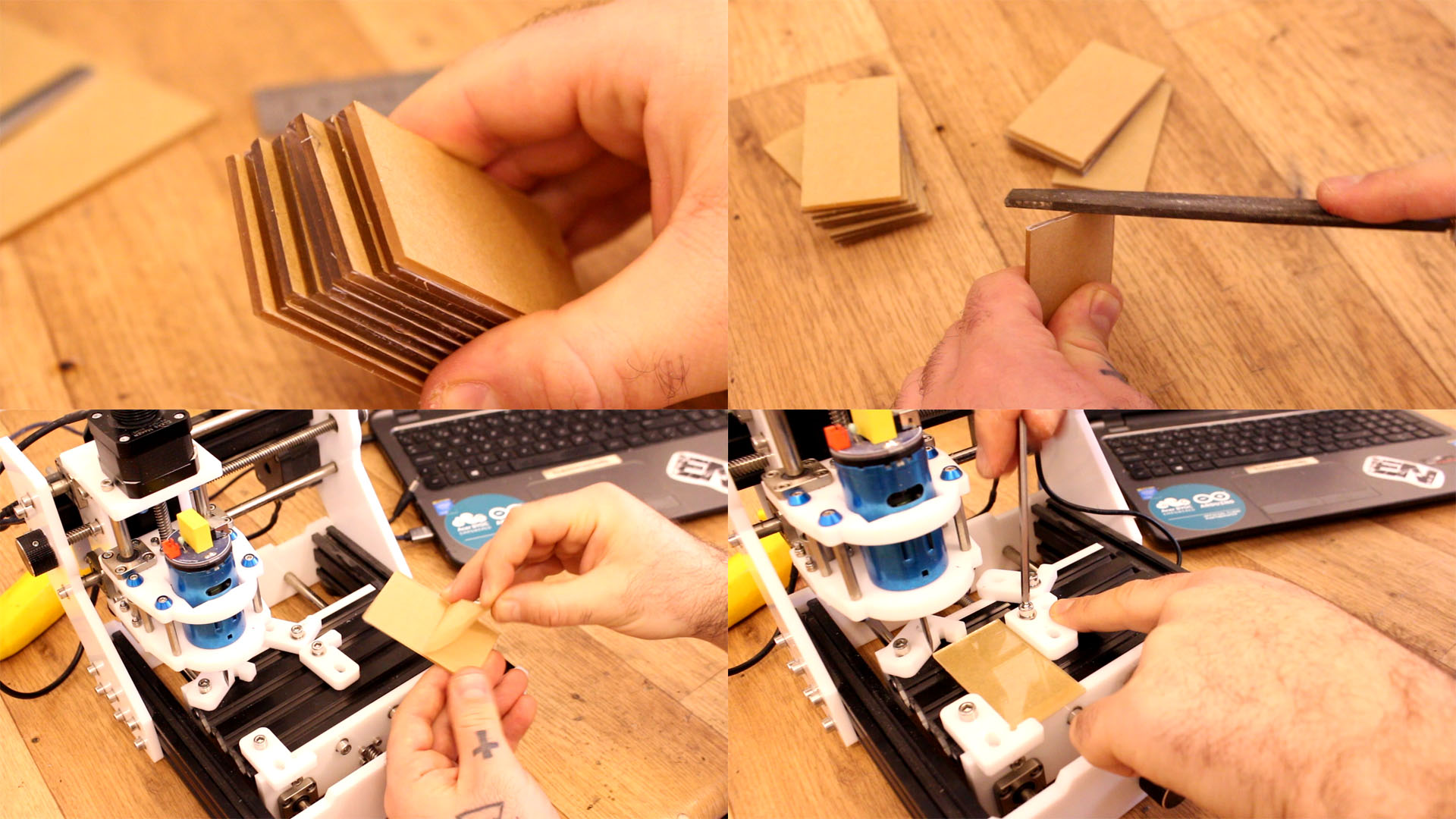
Get the 20x30cm Acrylic board and don't remove the protective paper yet. Mark lines for rectangles of 4x7cm. Then I use the cutter and a metal rule to engrave the cuts. Pass the cutter a few times, maybe 10 or 11 times. Then place the board between to wood plates and with the cut just on the edge. Press and the part should cut exactly where you've passed with the cutter.
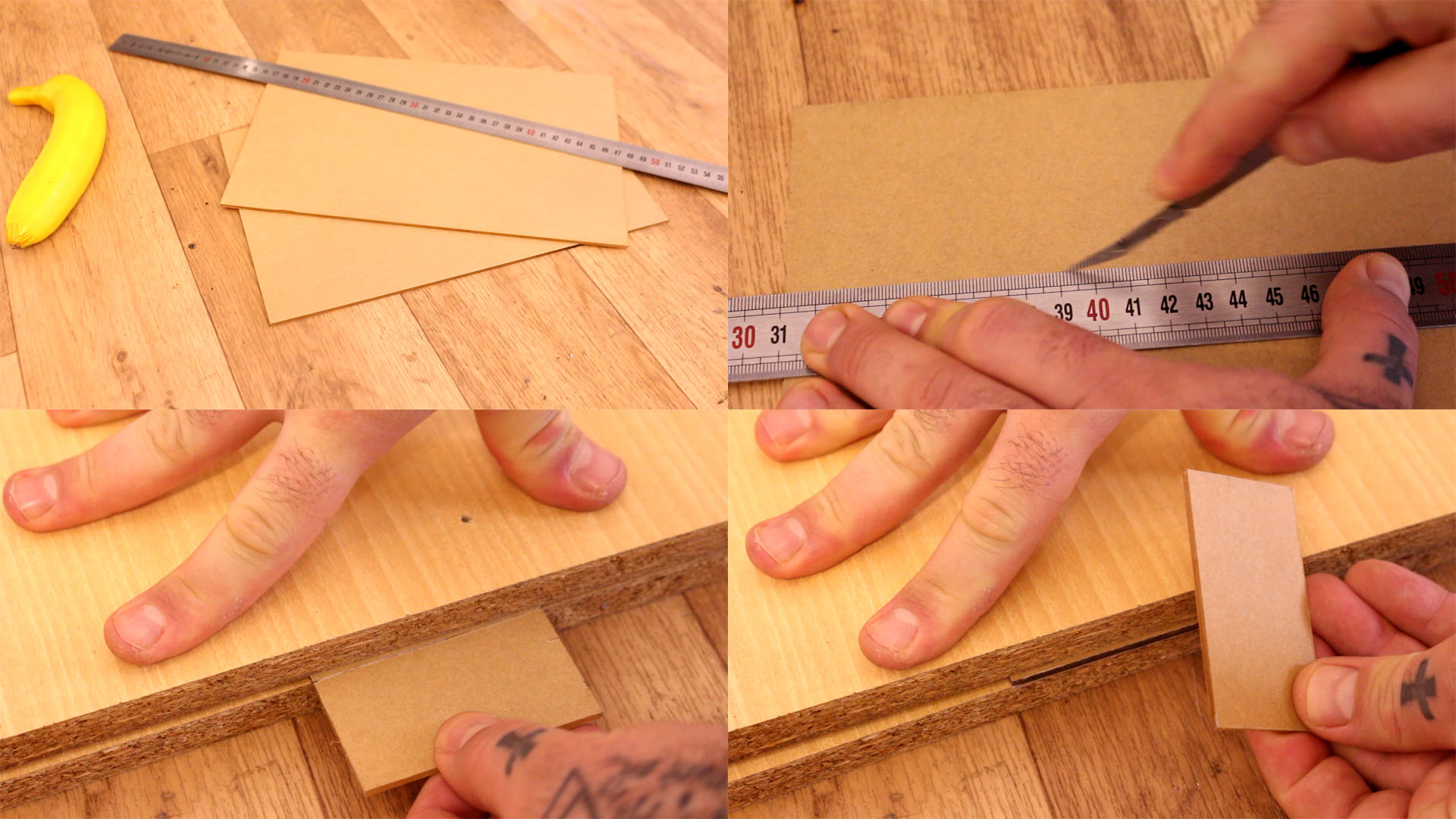
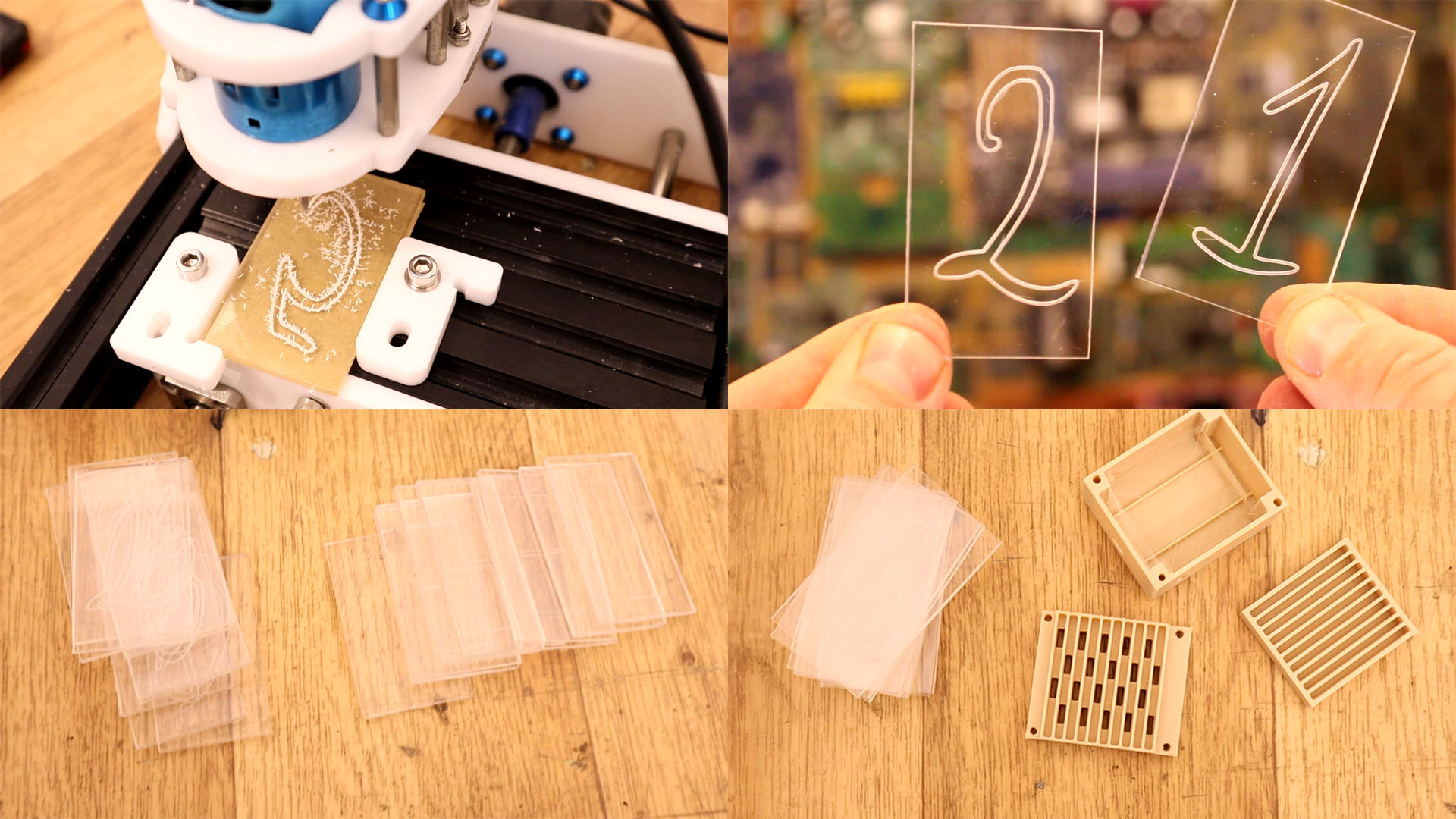
Now I have 10 acrylic boards of 4 by 7 cm. Pass some sanding paper in case that the cut is not good enough. Now we can peal just one side of the protective paper and fix the board in place on the CNC machine. You could do this manually as well. To make it manually, just mark the numbers with a marker and then use an engraving tool or a dremel and follow the line.
In case you use a CNC machine, download the G codes from below. In my case I use the Eleks Maker CNC engraver with the bCNC software. make sure the board is aligned with the Y axis and fix it in place. Open each G-code and engrave the number.
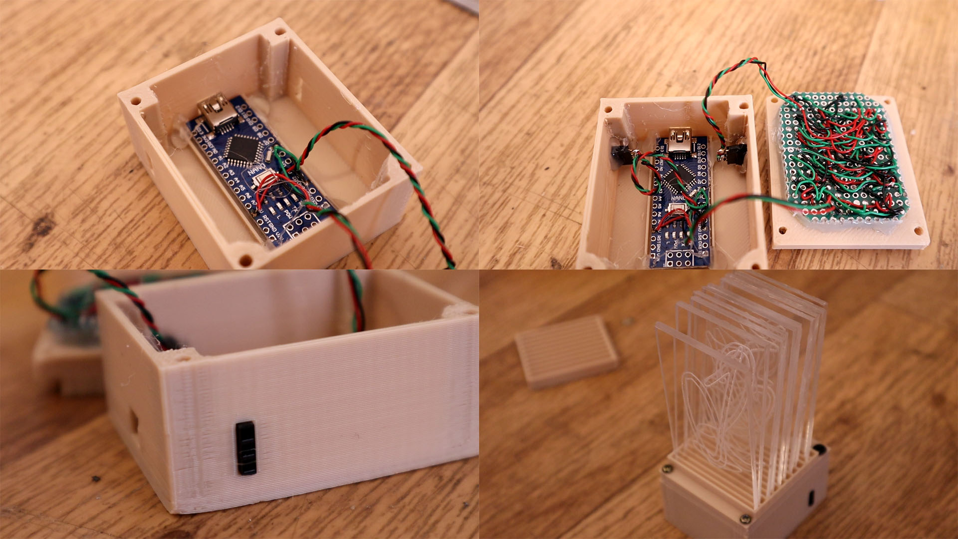
Now we have all numbers engraved on the 4 by 7cm acrylic boards. We have from 0 to 9. Is time to make the 3D case. Downlaod it from below. The case has 3 parts. The bottom case, the support for the acrylic boards with the LEDs holes and the top support. Print it with 2 perimeters, 20% infill and a 0.4mm nozzle. Use PLA material or PETG.
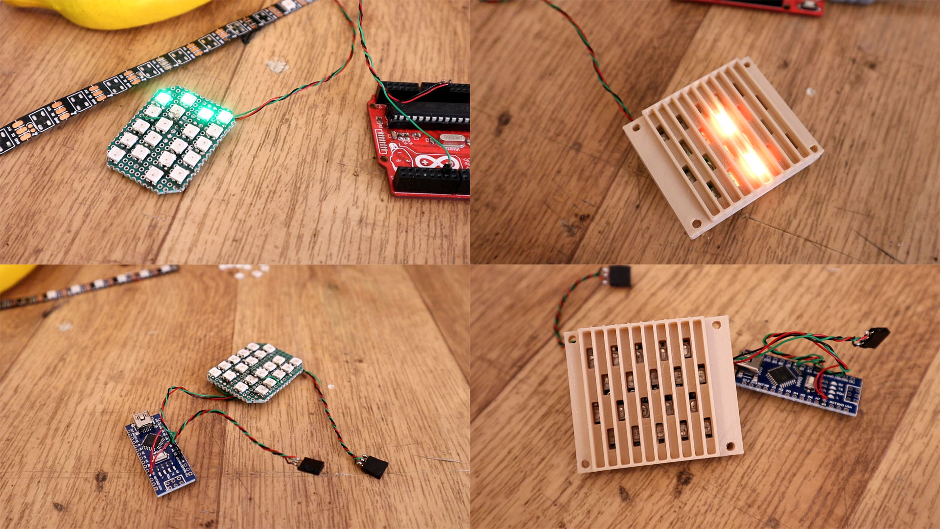
In my case I've used a DIY PCB. But you could downlaod the GERBERs above and order the PCB. Solder the LEDs, thw wires to the Arduino and to the female pins as you can see below and in the schematic using digital pin D6. Then screw or glue the PCB on the bottom side of the 3D part with the LEDs holes. Make sure the LEDs are exactly in front of the holes.
Now glue everything inside. Close the case with 2mm screws. Then add all the acrylic boards from 0 to 9. Now we can add the top side and just program the Arduino. For that go below adn downlaod the code and upload it to the Arduino. You will need the Adafruit library as well, so install taht to the Arduino IDE.
Downlaod the code. Connec the USB and uplaod it. You will need the Adafruit library as well, so install that to the Arduino IDE. Copy the code or dwonload it from below. This is just an example for only one display, so numbers from 0 to 9.
#include <Adafruit_NeoPixel.h>      //Downlaod it here: https://www.electronoobs.com/eng_arduino_Adafruit_NeoPixel.php
#ifdef __AVR__
 #include <avr/power.h> // Required for 16 MHz Adafruit Trinket
#endif


#define PIN        6 // I've used D6 to send the serial data


#define NUMPIXELS 20 // Because each display ahs 20 LEDs


Adafruit_NeoPixel pixels(NUMPIXELS, PIN, NEO_GRB + NEO_KHZ800);
#define DELAYVAL 500 // Time (in milliseconds) t

void setup() {
  // These lines are specifically to support the Adafruit Trinket 5V 16 MHz.
  // Any other board, you can remove this part (but no harm leaving it):
#if defined(__AVR_ATtiny85__) && (F_CPU == 16000000)
  clock_prescale_set(clock_div_1);
#endif
  // END of Trinket-specific code.
  pixels.begin(); // INITIALIZE NeoPixel strip object (REQUIRED)
}

void loop() {
  pixels.clear(); // Set all pixel colors to 'off'

  for(int i=0; i<NUMPIXELS; i++) { //


    pixels.setPixelColor(i, pixels.Color(0, 150, 0));   //Only green color. Values are R G B
    pixels.show();   // Send the updated pixel colors to the hardware.
    delay(DELAYVAL); // Pause before next pass through loop
  }
}//end of void loop