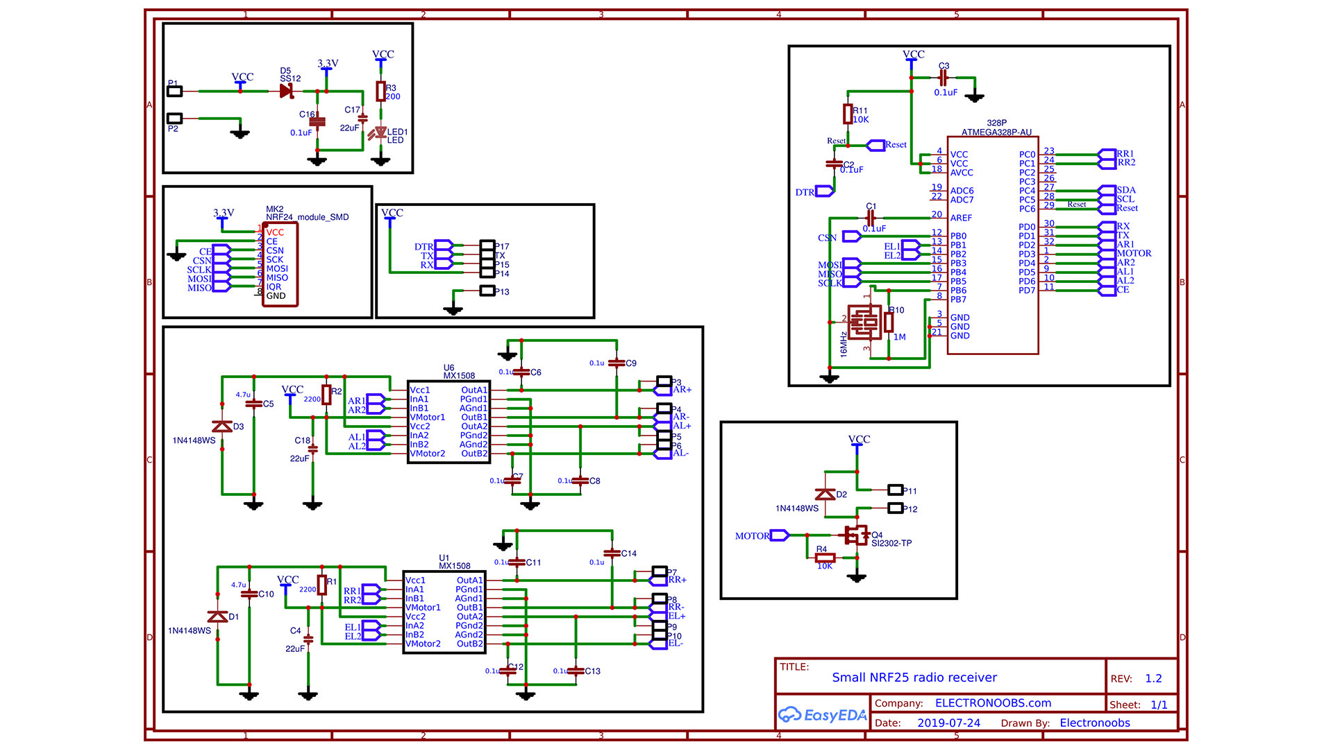
This is the simple schematic I've used for this project. First, we need the basic configuration of the ATMega chip, and for that we need the 16MHz resonaror, a few resistors for pullups and some capacitors. On the bottom left part of the scheamtic we have the configurations of the two H bridge ICs and on the right, a small MOSFET with a pulldown. On the top left corner we have the supply input and some pads for the NRF24 SMD radio mdoule. To get a lower voltage for this radio mdoule that works at 3.3V more or less, I've used just a simple diode.