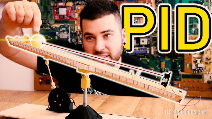
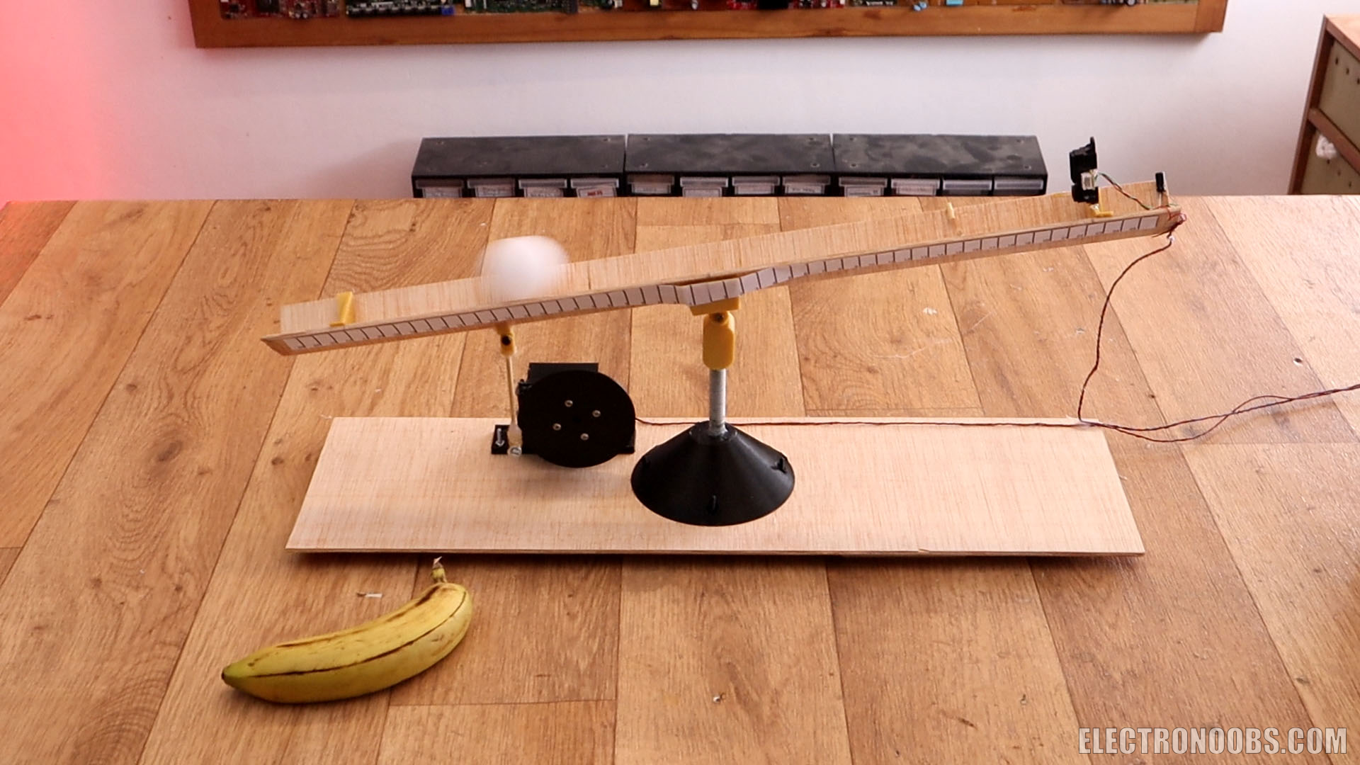
In this tutorial we will build this balance. It is controlled with a servo motor and an Arduino with a PID code. The idea is to get the ping pong ball in the middle. To do that we will use a IR distance sensor. By knowing the distance to the ball and using the PID code to move the servo, we could control the position and speed of the ball and stop it exactly in the middle. The system could get better with a better resolucion sensor and better ser
by: ELECTRONOOBS on 2026-06-10
The part list for this tutorial is simple. But we do need to make our balance. You could use your own parts for taht but I've used 3D printed parts. You could download that from the part list. You will also need some plywood to make the abse and the groove where the ball will roll. We also need a servo motor, in this case the Futaba S3003. Then we need the distance sensor. I finally use dht Sharp 2y0a21 becasue it had a higher range. We need some screws, wires and an Arduino, and that's it. Also, the ping pong ball.
We need:
- 2 x Arduino NANO/UNO: LINK eBay
- 1 x Sharp 2y0a21 sensor: LINK eBay
- 1 x Futaba S3003 servo: LINK eBay
- 3D parts: Download here
- Extra wire, M3 screws, solder, soldering-iron, breadboard, etc???
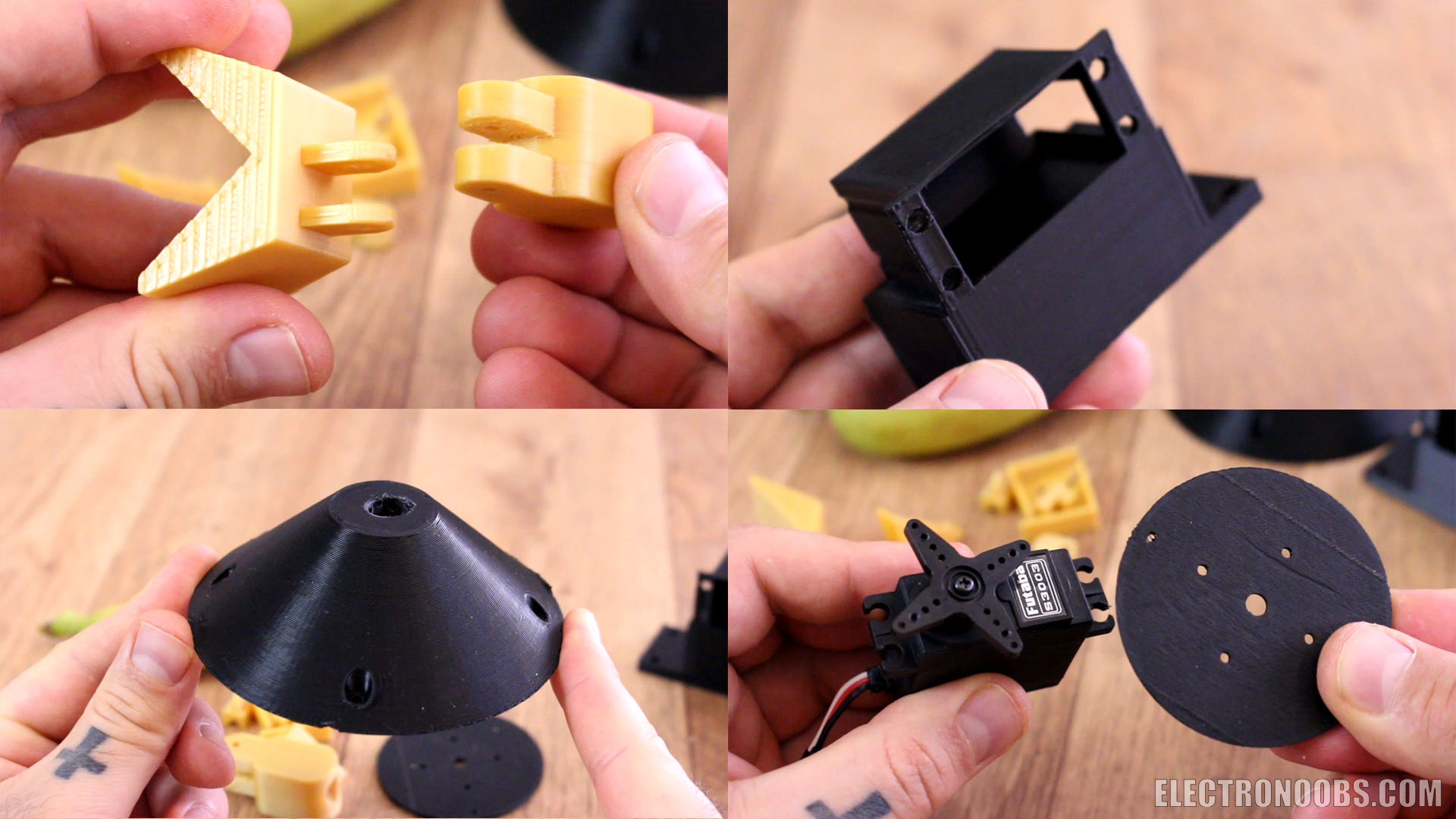
As for the screws, I've used a 10cm long M8 screw and all the rest are M3 screws. Print the 3D files with 2 perimeters, 20% infill, 0.4mm nozzle and 0.2mm layer height. You have different size wheels in order to have faster or slower movement. This will also affect the results.

Below you have the link to download the 3D files. You will have the main base, 2 big hinges for the balance, the support for the servo motor with holes for M3 screws and the disc that will be connected to the servo motor. For this you will have different sizes. You will also have some small parts to transfer the force from the servo to the balance, and that's it. The rest is made with plywood parts.
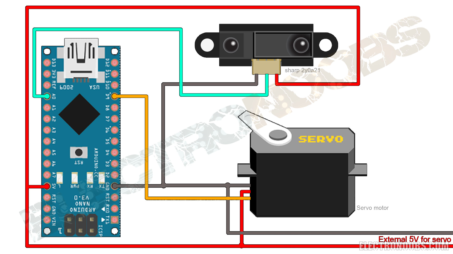
The scheamtic is more tahn simple. Just connect the servo motor to the D9 pin for the PWM signal. Supply 5V from external power supply because the Arduino can't supply enough current for the servo motor under load. Also, supply the IR sensor and connect the analog output on analog pin A0. And that's it, it is a very simple scheamtic. Make sure the sero will start in the middle position.
After you print the 3D files, cut 2 parts of plywood. Each of 40cm long and a width of around 2.5cm. Then glue thsoe together with a 90 angle in between adn then add the first hinge 3D printed part as you can see below. This will make our groove where the ball will swing side to side. Then add the second part of the ginge to the M8 screw. Place the main suppor on another piece of plywood and add that M8 screw. Now join these two parts together with a M3 scrw and the balacne is ready.
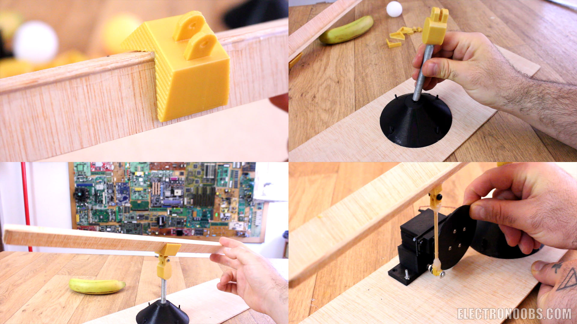
Place the servo motor inside the 3D printed support. Then add the disc to the servo motor. Using a barbeque wood stick and the small parts and some other m3 screws, transferr the rotation from the motor to the balance part. Measure the position more or less. Now the mechanical part is ready. Just add the end stops on the balance and glue the IR sensor on the right side. Make sure it doesn't have interference and that it can measure up to the other side of the balance. Connect everything to the Arduino and let's see the code.
Download the code from below. You don't need any library. Just uplaod it to the Arduino and start tunning the PID constants you can see below, kp, ki and kd. In my case I had good results with those values. Wathc the video in order to see how to tune each of the P, I and D constants. You have to start with P = 1 and the I and D equal to 0. Then follow the steps. Uplaod the code and connect the 5V power supply and add the ball. It should move and place the ball in the middle. Read the comments in the code for more. You must define the distance from the sensor to the middle of the balance.
///////////////////PID constants///////////////////////
float kp=8; //Mine was 8
float ki=0.2; //Mine was 0.2
float kd=3100; //Mine was 3100
float distance_setpoint = 21;           //Should be the distance from sensor to the middle of the bar in mm
float PID_p, PID_i, PID_d, PID_total;
///////////////////////////////////////////////////////Comments


Leave a comment
Please login in order to comment.