
 About me
  History
  Let's learn
  Contact us
  Arduino tutorials
 Circuits tutorials
  Robotics tutorials
 Q&A
Q&A Blog
Blog  Arduino
  Circuits
 Robotics
  Modules
  Gadgets
  Printers
  Materials
  3D objects
  3D edit
  Donate
  Reviews
  Advertising


Arduino Drone V2.0
 Drone construction
 Receiver PWM read
 IMU + PID control
 ESCs PWM write
3.0 IMU + PID control
3.1 IMU gyro read
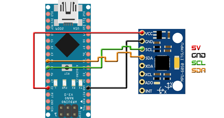
Ok, so the first thing to do is to connect the MPU6050 module as in the schematic below. Just supply 5 volts and connect GND. Next connect SDA to analog pin A4 of the Arduino and SCL to analogmpin A5. Those are the i2c data and clock pins of the Arduino in case of the UNO or NANO.
Ok, so now we have connected the IMU module to the Arduino. Let's write a small code in order to read just the gyro raw data for this example. Before we do that we have to understand how this module works. Once you activate the data read, it will store all the measurements into some registers. What we have to do is to read those registers. If we check the register map of this module we can see that registers 67 to 72 correspond to the gyro data. We only need the X and Y gyro data for now since I won't use the yaw axis in this part of the project.
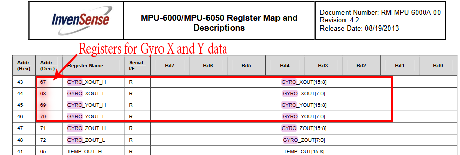
We can clearly see in the picture above that the data for the X and Y gyro values are stored in registers 67,68, 69 and 70. Ok, so probably you are asking why there are 4 values instead of just 2. Well, because each gyro or acceleration value is divided in 2 8 bit registers. So we have to read two registers and the combination of those two will give us the total value.
Ok so in the code, in order to communicate using i2c, we have to import the wire.h library. Once that is done we can start a new transmission. For that we need the i2c slave adress of the IMU module. If we check the MPU6050 datasheet we can see that that value is 68 in hexadecimal so (0x68). In the code below we can see how we start the new transmission and we write a 0 value into the 6B register. Then we start a new transmission and we configure the gyro range of 1000 degrees per seconds. To do that we send 00010000 or 0x10 to the 1B register as the datasheet tels us.
      Wire.begin();                           //begin the wire comunication
      Wire.beginTransmission(0x68);           //begin, Send the slave adress (in this case 68)
      Wire.write(0x6B);                       //make the reset (place a 0 into the 6B register)
      Wire.write(0x00);
      Wire.endTransmission(true);             //end the transmission

      Wire.beginTransmission(0x68);           //begin, Send the slave adress (in this case 68)
      Wire.write(0x1B);                       //We want to write to the GYRO_CONFIG register (1B hex)
      Wire.write(0x10);                       //Set the register bits as 00010000 (1000dps full scale)
      Wire.endTransmission(true);             //End the transmission with the gyro
Ok, now we have configured the gyro data. In the setup loop we also start the Serial with a baud rate of 9600 for future monitor prints of the values. At the same time we take a time stamp.
To read the data we start a new transmission and we send the dirrection of the first gyro data register, which is 43. Next we ask for 4 following registers starting with the 43. We store 4 values with both HIGH and LOW parts of the X and Y gyro data. Next we shift 8 bits the HIGH values of each axis and we combine the registers using the OR operation. Now we have the raw data read and store it in the Gyro_raw float variables.
      Wire.beginTransmission(0x68);            //begin, Send the slave adress (in this case 68)
      Wire.write(0x43);                        //First adress of the Gyro data
      Wire.endTransmission(false);
      Wire.requestFrom(0x68,4,true);           //We ask for just 4 registers

      Gyr_rawX=Wire.read()<<8|Wire.read();     //Once again we shif and sum
      Gyr_rawY=Wire.read()<<8|Wire.read();
But this are not the real gyro data which is a value of in speed in degrees per second. Once again, if we check the datasheet of the module we can see that we have to divide the raw value by 32.8 in order to obtain real values of degrees per second. I’ve selected the range of 1000 degree per second so for the FS_sel iqual to 2, you have to divide the value by 32.8. Ok, I do that and store the final data into the Gyro angle variables.
    Gyr_rawX=Wire.read()<<8|Wire.read();     //Once again we shif and sum
    Gyr_rawY=Wire.read()<<8|Wire.read();
    /*Now in order to obtain the gyro data in degrees/seconds we have to divide first
    the raw value by 32.8 because that's the value that the datasheet gives us for a 1000dps range*/
    /*---X---*/
    Gyr_rawX = (Gyr_rawX/32.8) - Gyro_raw_error_x;
    /*---Y---*/
    Gyr_rawY = (Gyr_rawY/32.8) - Gyro_raw_error_y;
If we read the data now we would notice that there is a initial error value. To remove that we should first make a few measurements, let's say 200, make the mean of those measurements and then substract the resulting value for each future measurement. We calculate the error in the setup loop and we start the void loop.
Ok so now we have the real degrees per second value. But we want degrees for this project. For that we have to multiply the values by the elapsed time between each measuremetn because degrees/second multiply by second equals to degrees. For that at the beginning of the void loop we make a time measurement and calculate the elapsed time as we can see below. Finally we multiply the Gyro raw data by the elapsed time and we integrate the value for each loop and we obtain the inclination angle and store it into the Gyro_angle_x or y variable.
    /*Now we integrate the raw value in degrees per seconds in order to obtain the angle
    * If you multiply degrees/seconds by seconds you obtain degrees */
    /*---X---*/
    Gyro_angle_x = Gyro_angle_x  + Gyr_rawX*elapsedTime;
    /*---X---*/
    Gyro_angle_y = Gyro_angle_y  + Gyr_rawY*elapsedTime;
Download the FULL
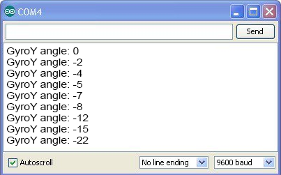
Ok, now we use the Serial.print() function to print the angle value. Upload the code above to the Arduino, make the IMU connections and open the serial monitor. Set the baud rate to 9600 and start moving the module. First live the module flat on the table and observe if you have a 0 or almost 0 angle value.
3.2.1 IMU Acc read
Download the
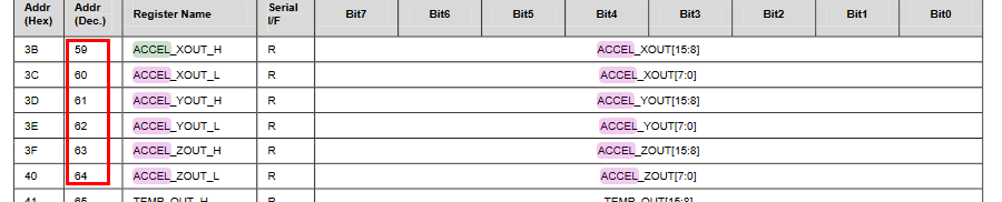
Now we have the gyro data. For the acceleration we have to do exactly the same but for 6 other registers. In this case we do need both X and Y axis accelerations but also the Z axis acceleration. For that we have to read the registers below starting with register 59.
As before we shift 8 bits the HIGH values and obtain the full acceleration raw data for X, Y and Z axis. Now we heve to divide this value by 4096 as the datasheet tels us for a range of +-8g.
  Wire.beginTransmission(0x68);     //begin, Send the slave adress (in this case 68)
  Wire.write(0x3B);                 //Ask for the 0x3B register- correspond to AcX
  Wire.endTransmission(false);      //keep the transmission and next
  Wire.requestFrom(0x68,6,true);    //We ask for next 6 registers starting withj the 3B
  //If we read the datasheet, for a range of+-8g, we have to divide the raw values by 4096
  Acc_rawX=(Wire.read()<<8|Wire.read())/4096.0 ; //each value needs two registres
  Acc_rawY=(Wire.read()<<8|Wire.read())/4096.0 ;
  Acc_rawZ=(Wire.read()<<8|Wire.read())/4096.0 ;
3.2.2 Euler angles
Ok, so now we have the acc raw data. How do we obtain the angle? Well using the Euler formula below. This formula uses the X, Y and Z accelerations in g to obtain the inclination angle.
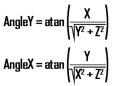
So that's exactly what we will do in the next part of the code. We apply the mathematics and obtain the angle using acceleration data. Remember that for this values we should also calculate the data error first in the Setup loop.
 /*Now in order to obtain the Acc angles we use euler formula with acceleration values
 after that we substract the error value found before*/
 /*---X---*/
 Acc_angle_x = (atan((Acc_rawY)/sqrt(pow((Acc_rawX),2) + pow((Acc_rawZ),2)))*rad_to_deg) - Acc_angle_error_x;
 /*---Y---*/
 Acc_angle_y = (atan(-1*(Acc_rawX)/sqrt(pow((Acc_rawY),2) + pow((Acc_rawZ),2)))*rad_to_deg) - Acc_angle_error_y;
3.3 Full angle read
Download the
Finally we have both the angle obtained with gyro data and the angle with Acc data. We should apply a complementary filter between this two values and obtain a better result. In the next part of the code we apply the complementary filter and we obtain the final angle value.
 //////////////////////////////////////Total angle and filter/////////////////////////////////////
 /*---X axis angle---*/
 Total_angle_x = 0.98 *(Total_angle_x + Gyro_angle_x) + 0.02*Acc_angle_x;
 /*---Y axis angle---*/
 Total_angle_y = 0.98 *(Total_angle_y + Gyro_angle_y) + 0.02*Acc_angle_y;
Download the FULL code above and upload it to the Arduino. Make the same connection for the IMU and open the serial monitor. Move the IMU around and observe the angle. Now in the next part we start the PID algorithm so let's get with it.
Ok, now that we have the angle read, let's see how to create the PID control.