The air conditioner in a central heating and cooling system provides cool air through ductwork inside your home, by providing a process that draws out the warm air inside, removing its heat. ... From that point, the condenser or outdoor unit then turns the refrigerant vapor back into a liquid, removing any heat.
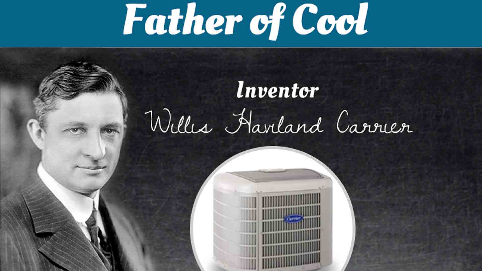
The first modern air conditioning system was developed in 1902 by a young electrical engineer named Willis Haviland Carrier. It was designed to solve a humidity problem at the Sackett-Wilhelms Lithographing and Publishing Company in Brooklyn, N.Y. Paper stock at the plant would sometimes absorb moisture from the warm summer air, making it difficult to apply the layered inking techniques of the time. Carrier treated the air inside the building by blowing it across chilled pipes. The air cooled as it passed across the cold pipes, and since cool air can't carry as much moisture as warm air, the process reduced the humidity in the plant and stabilized the moisture content of the paper. Reducing the humidity also had the side benefit of lowering the air temperature -- and a new technology was born.
Carrier realized he'd developed something with far-reaching potential, and it wasn't long before air-conditioning systems started popping up in theaters and stores, making the long, hot summer months much more comfortable. The actual process air conditioners use to reduce the ambient air temperature in a room is based on a very simple scientific principle. The rest is achieved with the application of a few clever mechanical techniques. Actually, an air conditioner is very similar to another appliance in your home -- the refrigerator. Air conditioners don't have the exterior housing a refrigerator relies on to insulate its cold box. Instead, the walls in your home keep cold air in and hot air out. Let's go on and discover what happens to all that hot air when you use your air conditioner.
Air conditioners use refrigeration to chill indoor air, taking advantage of a remarkable physical law: When a liquid converts to a gas (in a process called phase conversion), it absorbs heat. Air conditioners exploit this feature of phase conversion by forcing special chemical compounds to evaporate and condense over and over again in a closed system of coils. The compounds involved are refrigerants that have properties enabling them to change at relatively low temperatures. Air conditioners also contain fans that move warm interior air over these cold, refrigerant-filled coils. In fact, central air conditioners have a whole system of ducts designed to funnel air to and from these serpentine, air-chilling coils.
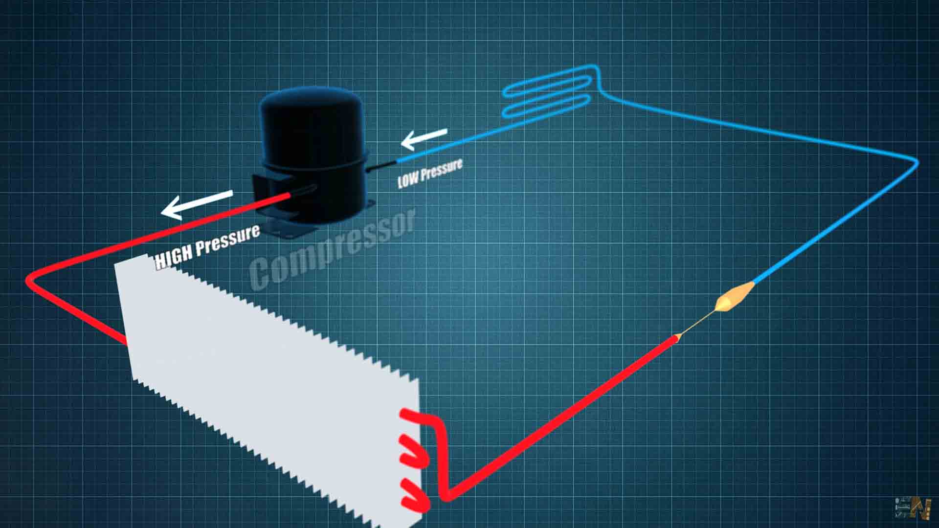
When hot air flows over the cold, low-pressure evaporator coils, the refrigerant inside absorbs heat as it changes from a liquid to a gaseous state. To keep cooling efficiently, the air conditioner has to convert the refrigerant gas back to a liquid again. To do that, a compressor puts the gas under high pressure, a process that creates unwanted heat. All the extra heat created by compressing the gas is then evacuated to the outdoors with the help of a second set of coils called condenser coils, and a second fan. As the gas cools, it changes back to a liquid, and the process starts all over again. Think of it as an endless, elegant cycle: liquid refrigerant, phase conversion to a gas/ heat absorption, compression and phase transition back to a liquid again. It's easy to see that there are two distinct things going on in an air conditioner. Refrigerant is chilling the indoor air, and the resulting gas is being continually compressed and cooled for conversion back to a liquid again. On the next page, we'll look at how the different parts of an air conditioner work to make all that possible.
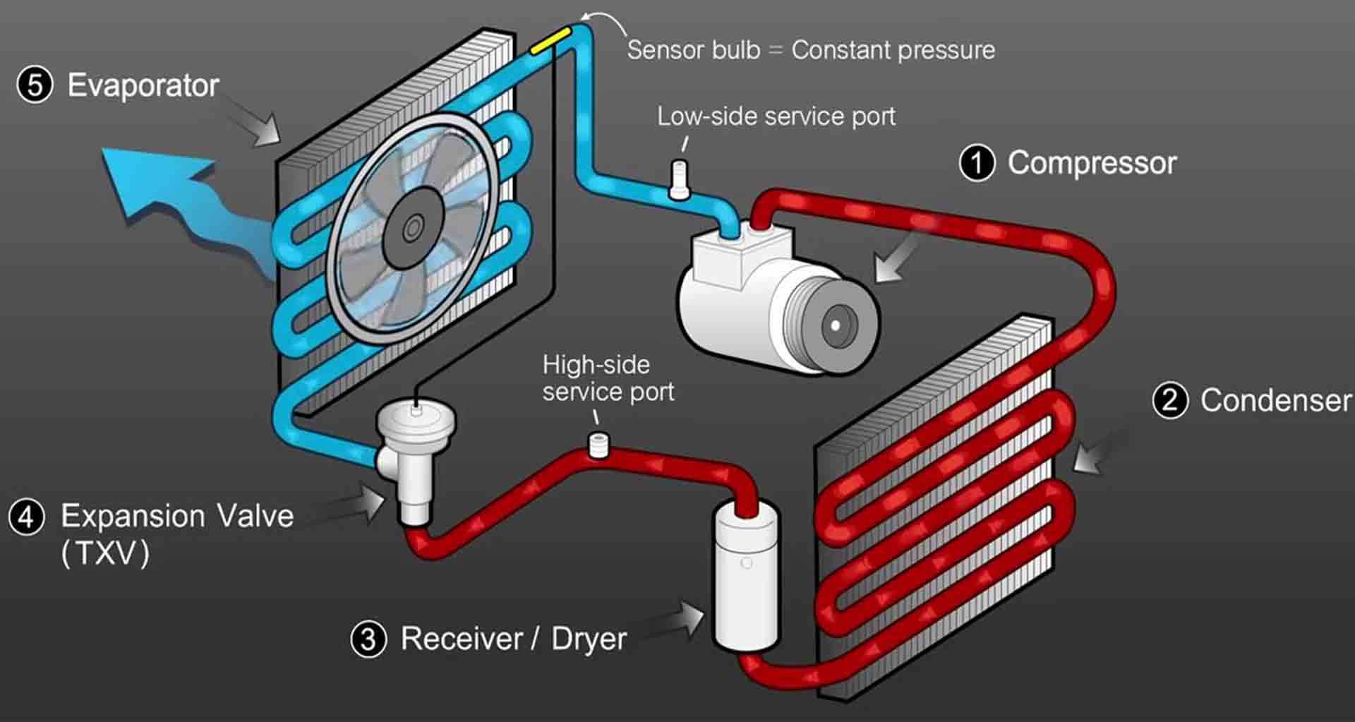
Let's get some housekeeping topics out of the way before we tackle the unique components that make up a standard air conditioner. The biggest job an air conditioner has to do is to cool the indoor air. That's not all it does, though. Air conditioners monitor and regulate the air temperature via a thermostat. They also have an onboard filter that removes airborne particulates from the circulating air. Air conditioners function as dehumidifiers. Because temperature is a key component of relative humidity, reducing the temperature of a volume of humid air causes it to release a portion of its moisture. That's why there are drains and moisture-collecting pans near or attached to air conditioners, and why air conditioners discharge water when they operate on humid days. Still, the major parts of an air conditioner manage refrigerant and move air in two directions: indoors and outside:
Evaporator - Receives the liquid refrigerant
Condenser - Facilitates heat transfer
Expansion valve - regulates refrigerant flow into the evaporator
Compressor - A pump that pressurizes refrigerant
The cold side of an air conditioner contains the evaporator and a fan that blows air over the chilled coils and into the room. The hot side contains the compressor, condenser and another fan to vent hot air coming off the compressed refrigerant to the outdoors. In between the two sets of coils, there's an expansion valve. It regulates the amount of compressed liquid refrigerant moving into the evaporator. Once in the evaporator, the refrigerant experiences a pressure drop, expands and changes back into a gas. The compressor is actually a large electric pump that pressurizes the refrigerant gas as part of the process of turning it back into a liquid. There are some additional sensors, timers and valves, but the evaporator, compressor, condenser and expansion valve are the main components of an air conditioner.
Although this is a conventional setup for an air conditioner, there are a couple of variations you should know about. Window air conditioners have all these components mounted into a relatively small metal box that installs into a window opening. The hot air vents from the back of the unit, while the condenser coils and a fan cool and re-circulate indoor air. Bigger air conditioners work a little differently: Central air conditioners share a control thermostat with a home's heating system, and the compressor and condenser, the hot side of the unit, isn't even in the house. It's in a separate all-weather housing outdoors. In very large buildings, like hotels and hospitals, the exterior condensing unit is often mounted somewhere on the roof.
A window air conditioner unit implements a complete air conditioner in a small space. The units are made small enough to fit into a standard window frame. You close the window down on the unit, plug it in and turn it on to get cool air. If you take the cover off of an unplugged window unit, you'll find that it contains:
A compressor
An expansion valve
A hot coil (on the outside)
A cold coil (on the inside)
Two fans
A control unit
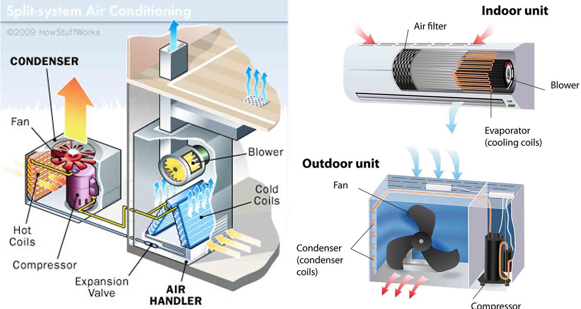
The fans blow air over the coils to improve their ability to dissipate heat (to the outside air) and cold (to the room being cooled). When you get into larger air-conditioning applications, its time to start looking at split-system units. A split-system air conditioner splits the hot side from the cold side of the system, as in the diagram below. The cold side, consisting of the expansion valve and the cold coil, is generally placed into a furnace or some other air handler. The air handler blows air through the coil and routes the air throughout the building using a series of ducts. The hot side, known as the condensing unit, lives outside the building.
The unit consists of a long, spiral coil shaped like a cylinder. Inside the coil is a fan, to blow air through the coil, along with a weather-resistant compressor and some control logic. This approach has evolved over the years because it's low-cost, and also because it normally results in reduced noise inside the house (at the expense of increased noise outside the house). Other than the fact that the hot and cold sides are split apart and the capacity is higher (making the coils and compressor larger), there's no difference between a split-system and a window air conditioner. In warehouses, large business offices, malls, big department stores and other sizeable buildings, the condensing unit normally lives on the roof and can be quite massive. Alternatively, there may be many smaller units on the roof, each attached inside to a small air handler that cools a specific zone in the building. In larger buildings and particularly in multi-story buildings, the split-system approach begins to run into problems. Either running the pipe between the condenser and the air handler exceeds distance limitations (runs that are too long start to cause lubrication difficulties in the compressor), or the amount of duct work and the length of ducts becomes unmanageable. At this point, it's time to think about a chilled-water system.
Most air conditioners have their capacity rated in British thermal units (Btu). A Btu is the amount of heat necessary to raise the temperature of 1 pound (0.45 kilograms) of water one degree Fahrenheit (0.56 degrees Celsius). One Btu equals 1,055 joules. In heating and cooling terms, one ton equals 12,000 Btu. A typical window air conditioner might be rated at 10,000 Btu. For comparison, a typical 2,000-square-foot (185.8 square meters) house might have a 5-ton (60,000-Btu) air conditioning system, implying that you might need perhaps 30 Btu per square foot. These are rough estimates. To size an air conditioner accurately for your specific application, you should contact an HVAC contractor.
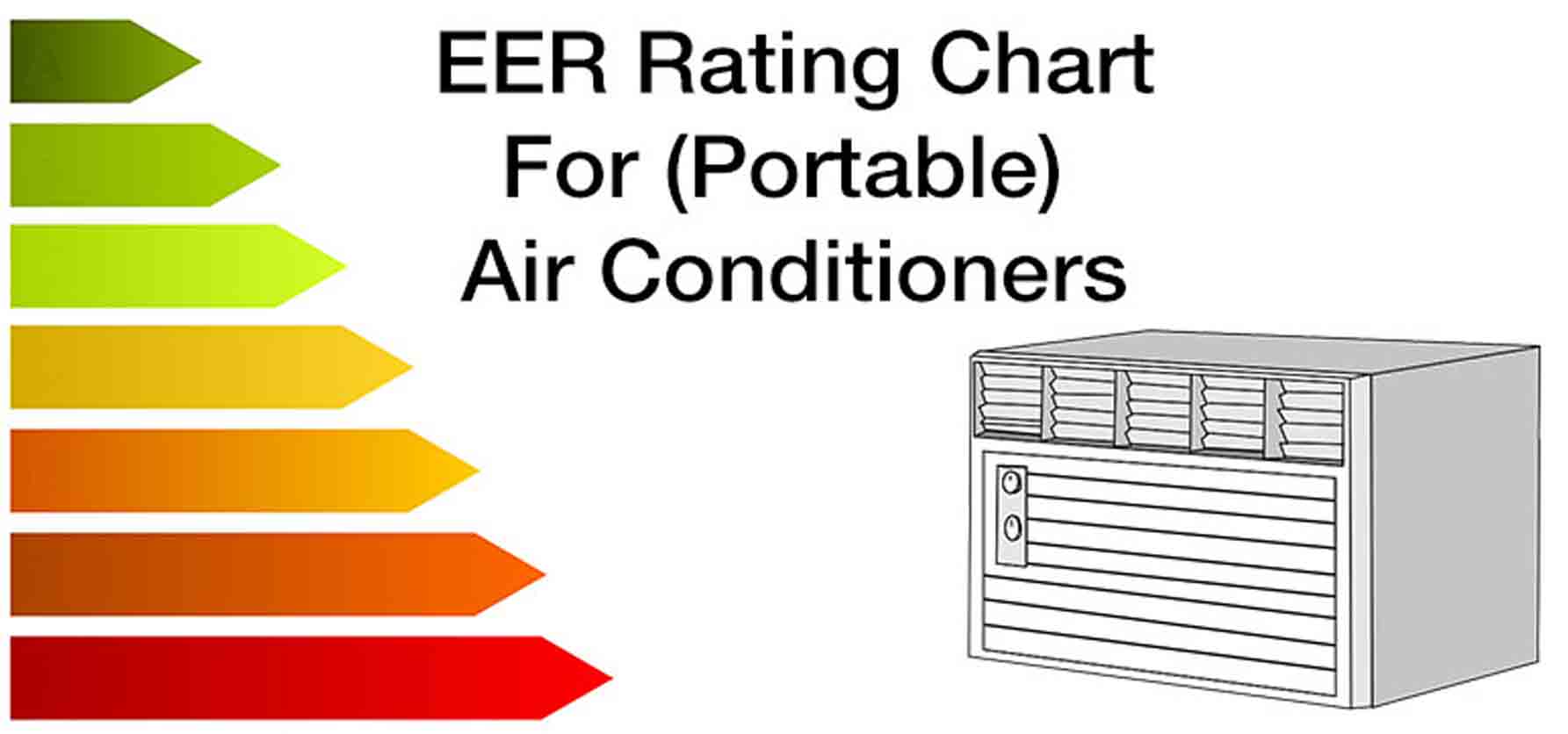
The energy efficiency rating (EER) of an air conditioner is its Btu rating over its wattage. As an example, if a 10,000-Btu air conditioner consumes 1,200 watts, its EER is 8.3 (10,000 Btu/1,200 watts). Obviously, you would like the EER to be as high as possible, but normally a higher EER is accompanied by a higher price. Let's say you have a choice between two 10,000-Btu units. One has an EER of 8.3 and consumes 1,200 watts, and the other has an EER of 10 and consumes 1,000 watts. Let's also say that the price difference is $100. To determine the payback period on the more expensive unit, you need to know approximately how many hours per year you will be operating the air conditioner and how much a kilowatt-hour (kWh) costs in your area. Assuming you plan to use the air conditioner six hours a day for four months of the year, at a cost of $0.10/kWh. The difference in energy consumption between the two units is 200 watts. This means that every five hours the less expensive unit will consume one additional kWh (or $0.10) more than the more expensive unit.
Let's do the math: With roughly 30 days in a month, you're operating the air conditioner:
4 months x 30 days per month x 6 hours per day = 720 hours
[(720 hours x 200 watts) / (1000 watts/kilowatt)] x $0.10/kilowatt hours = $14.40
The more expensive air conditioning unit costs $100 more to purchase but less money to operate. In our example, it'll take seven years for the higher priced unit to break even.