
This is a simple latch circuit. Press the button once and it will turn on the output. Press the button again, and it will turn off the output. Instead of a push button, you can use a vibration sensor for example, and turn on your devices with the latch each time you sense a vibration. See below the schematic and values for the circuit.
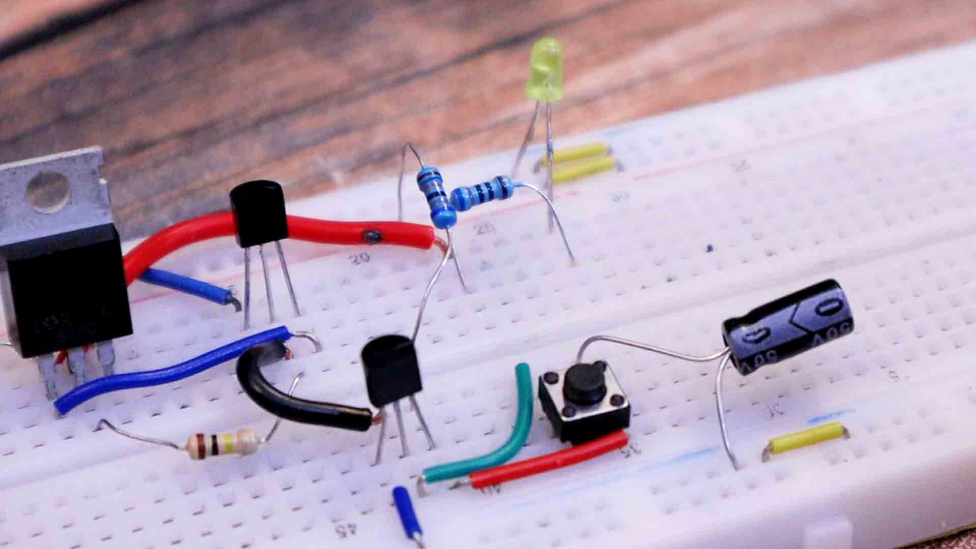
Below you have all the parts needed for this circuit, and on the next step you have the schematic. You can test this circuit on a breadboard or maybe solder it directly to a small prototyping PCB. You can also add an extra LED with a 100 ohm resistor at the output, so you can see when the output is ON or OFF.
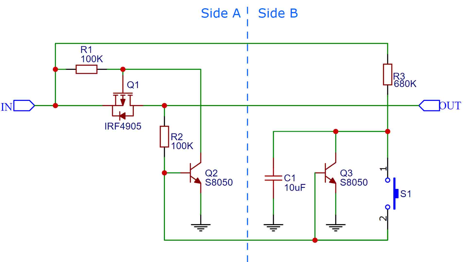
Below you have the schematic I've used. When you power the circuit, all transistors are OFF. The Q1 MOSFET is the one that enables the output, so the current path from IN to OUT. Let's center first on the Q2 BJT transistor. When you push the button, as you can see, that will connect the R3 to the base of the Q2 transistor. Since R3 is a pullup connected directly at the input, this will turn ON the Q2 transistor. Since Q2 is now ON, there is a path to ground from the gate of the Q1 MOSFET. Since that is a P-type, it will now turn on because we have connected its gate to GND. So the output is now ON, great.
But wait, the Q3 BJT is also connected with the base to the push button. So at the same time, this BJT will also turn ON. The collector of this transistor is also connected to taht R3 resistor and the C1 capacitor. So, since now this Q3 is ON and creates a path to ground, the C1 which was previously charged up by the R3 resistor, will now discharge to GND. So, the next time we push the button, the voltage at R3 wont be high anymore, it will be low. So the second time we push the button it will apply low signal at the bases of Q2 and Q3 and by that they turn OFF. Then the cycle repeats since now C1 can charge back to high value. That's how we can latch the circuit ON and OFF.
See below the test. Push once and the output is HIGH. Push a second time and the circuit output is LOW and then we can repeat the process. Instead of a push button you can add a vibration sensor like this one here, that has two contacts inside that will touch when the sensor vibrates. With that you could for example wake up a microcontroller, do a process and then go back to sleep and consume 0 power. That's exactly what we will do in the next tutorial so check that out.


