It’s not unheard of for those who tinker in the land of electronics to suddenly find themselves with a project on their hands and potential customers clamoring at the door. Of course, the road to shipping a product is a long one, and requires a unique set of skills quite distinct from those required to build the initial prototype. In developing a product for Airsoft use, [bald greg] realized that a testing rig would be key to ensuring their hundreds of units left the building in working condition.
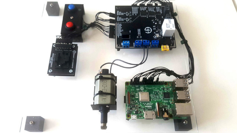
When shipping units in the hundreds rather than thousands, keeping overheads low is key to maintain a sustainable profit margin on each unit sold. Thus, [bald greg] built a rig that would allow for effective testing of devices rather than breaking the bank. The rig also handles programming, saving the cost of purchasing pre-programmed microcontrollers from the manufacturer. A Raspberry Pi runs the show, using its GPIO pins to program boards and saving test results and serial numbers for later reference. A bed of nails fixture is used to connect to each individual board. Additionally, to test each board as realistically as possible, hardware mimicking a real Airsoft electric pistol is used to properly load the hardware.
[bald greg]’s work is a great example of approaching QC on a budget, and we suspect he’ll sleep soundly knowing the boards in the mail are going to work first time. We’ve seen others take similar approaches, too. If you’re working on your own production testing rig, be sure to let us know!
The rig was made using some basic tools as well as a 3D printer. A 3mm PMMA plate was used as a base, to which all of the components were mounted. Black blocks that can be seen in each corner are just 3D printed stands screwed to the PMMA plate.
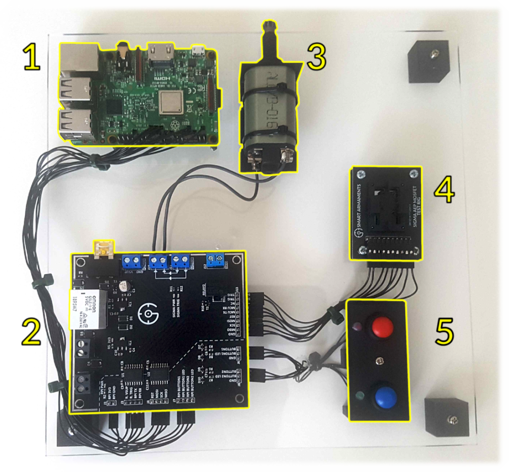
The rig consists of:
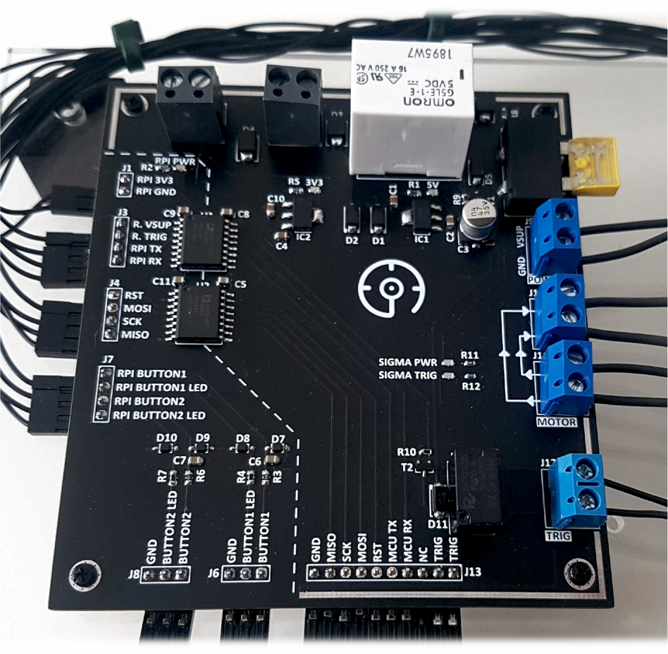
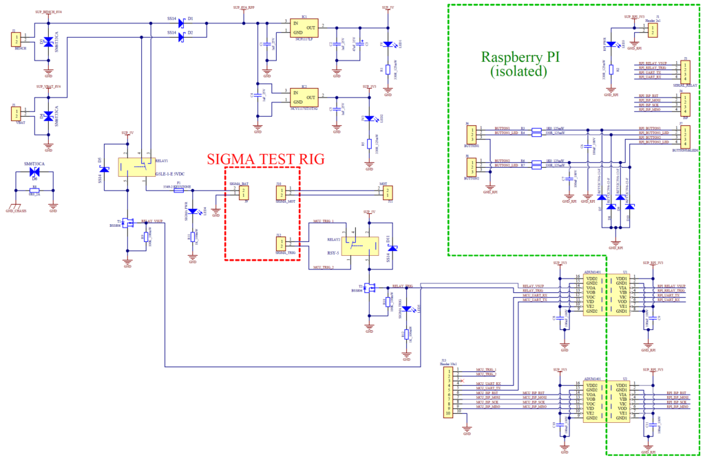
This circuit consists of relays, fuse, power supply (3V3 & 5V LDOs), ESD protection, flyback diodes, and last but not least, digital signal isolation. Green connectors are used for connecting the power supply (either battery or bench power supply) while blue connectors are intended for the device under test. Minimum 4 wires have to be connected (2 per power and 2 per load) because they are designed to carry high current (tens of amperes). TRIG signals are optional because these signals can be connected through pogo pins on the bed of nails.
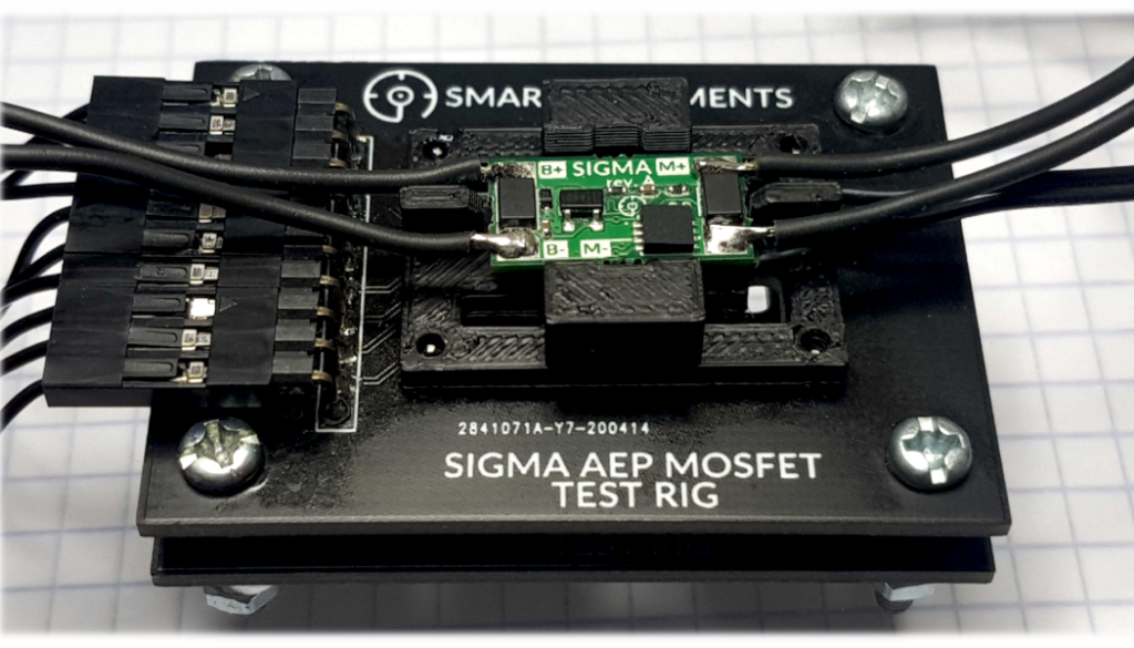
The whole process (flashing, testing, and validation) takes ~30 seconds to complete. The bed of nails turned out to bring the most issues and it is still far away from a perfect solution. Some issues simply came from our product’s small test points (1mm). Unfortunately, due to component density and small PCB dimensions, it was not possible to use through-hole test points there. At the end of the day, it’s important to notice that the rig works just fine and automates the work perfectly. The test rig operator’s job is now to: