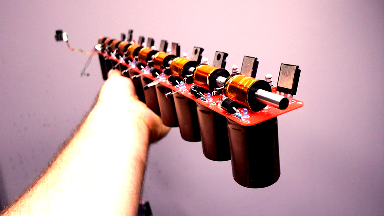


This, is version 2 of my very powerful coilgun but I'm working on version 3. As you can see, is huge and it has quite some power and works with high voltage, so please, I can’t stress this enough. Never touch the high voltage parts, stay insulated, use proper tools and if you don’t know what you’re doing, don’t try this project, just watch the video for learning purposes. That being said, in this video I will show you the improvements from the previous version, I will rectify a small error I’ve told you in the previous video, I will show you the schematic, we design the new PCB, we check the part list and assemble the board. Finally, we test it and I also want to design a 3D case for it so it would look better than before. So guys, stay safe and protected and let’s get started.
Part 1 - Schematic
This is the schematic for this project. Basically, we have the first stage which is a bit different and then the second to the tenth stage is all the same. The first stage is different because it has the push button activation, the 450V input and 12V. The rest of the stages are using infrared light to trigger the magnetic field so they don’t need the push button part. In Altium designer, I update the PCB and start placing the components. There are a lot of them but since the stages are all the same, is a very repeating process. All you have to make sure is that the distance between the coils on the PCB is 45mm and for the infrared LEDs as well. The LEDs that have the arrow must be face to face because these are the detectors.
Part 2 - The PCB
For the high voltage tracks ground and 450V, I use very thick tracks in order to withstand enough power (>4mm width). And then, the rest of the tracks for signal and 12V, are using just 1 mm tracks. And that’s it, the PCB is ready, but this time with 10 coils and it has a size of 47 cm long by 5 cm.
I generate the GERBERs and go to PCBWAY.com. Insert the PCB size and click quote now button. Here I select the red color for the soldermask. I add to cart and on the next page I upload the GERBERs generated with Altium. Submit the order and receive the PCBs in just a few days. They look awesome. I know that the black finish is my favorite but I also like the red color, it looks great, right? So, if you want to try my project, download the GERBERs for free.
So, we need PCBs, the high voltage capacitors, we also need Thyristors. We need some infrared LEDs and some phototransistors. We also need some BJT transistors. The rest are some resistors and some LEDs. We also need the copper coils. To make these you can download from below my 3D design. Remove the supports and you will be left with a basic support. Then you can add around 150 loops using thick enameled copper wire (0.8-0.9mm) that could withstand enough current. Once you have all the loops, you can add some KEPTON tape on top so the coil will stay that way. Or if you think that’s too much work, you can find these coils to buy on the internet, see below. We also need some powerful diodes and some push buttons to fire the gun. On the other side we need the high voltage module and maybe a 3S battery or even better a battery socket. As projectiles I will use some 6 to 7mm metal rods that you could cut to around 2cm and maybe smooth the edges. As the gun barrel, I will use an 8 mm metal tube. It would be better to use a plastic tube so there would be less magnetic attraction and less friction with the bullet. You have to make holes on this tube from side to side
Obviously, you can always add more stages and make it of 8, 9, 10 or even more stages but I guess there will be a speed limit given by the speed of the component commutation. Since you now have my design of separated stage, you can always solder one more if you want. But even so, the bullet is very fast. So guys, I hope that you like this project and have in mind this is just the first version. In a future video I will make a case for the electronics, create a support for the gun and give it a better look so stay tuned for that. If my videos help you, consider supporting my work on my PATREON or a donation on my PayPal. Thanks again and see you later guys.