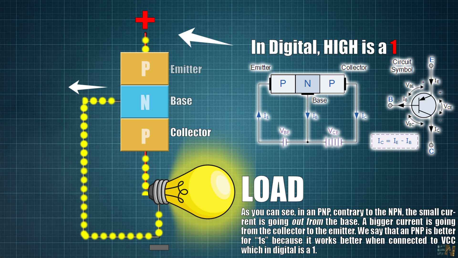


Basically, in this type of transistor construction the two diodes are reversed with respect to the NPN type giving a Positive-Negative-Positive type of configuration, with the arrow which also defines the Emitter terminal this time pointing inwards in the transistor symbol.
Also, all the polarities for a PNP transistor are reversed which means that it “sinks” current into its Base as opposed to the NPN transistor which “sources” current through its Base. The main difference between the two types of transistors is that holes are the more important carriers for PNP transistors, whereas electrons are the important carriers for NPN transistors.
Then, PNP transistors use a small base current and a negative base voltage to control a much larger emitter-collector current. In other words for a PNP transistor, the Emitter is more positive with respect to the Base and also with respect to the Collector.
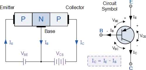
The construction of a “PNP transistor” consists of two P-type semiconductor materials either side of an N-type material as shown on the side.
he construction and terminal voltages for an NPN transistor are shown above. The PNP Transistor has very similar characteristics to their NPN bipolar cousins, except that the polarities (or biasing) of the current and voltage directions are reversed for any one of the possible three configurations looked at in the first tutorial, Common Base, Common Emitter and Common Collector.

PNP Transistor Connection
The voltage between the Base and Emitter ( VBE ), is now negative at the Base and positive at the Emitter because for a PNP transistor, the Base terminal is always biased negative with respect to the Emitter.
Also the Emitter supply voltage is positive with respect to the Collector ( VCE ). So for a PNP transistor to conduct the Emitter is always more positive with respect to both the Base and the Collector.
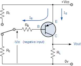
The voltage sources are connected to a PNP transistor are as shown. This time the Emitter is connected to the supply voltage VCC with the load resistor, RL which limits the maximum current flowing through the device connected to the Collector terminal. The Base voltage VB which is biased negative with respect to the Emitter and is connected to the Base resistor RB, which again is used to limit the maximum Base current.
To cause the Base current to flow in a PNP transistor the Base needs to be more negative than the Emitter (current must leave the base) by approx 0.7 volts for a silicon device or 0.3 volts for a germanium device with the formulas used to calculate the Base resistor, Base current or Collector current are the same as those used for an equivalent NPN transistor and is given as.

We can see that the fundamental differences between a NPN Transistor and a PNP Transistor is the proper biasing of the transistors junctions as the current directions and voltage polarities are always opposite to each other. So for the circuit above: Ic = Ie – Ib as current must leave the Base.
Generally, the PNP transistor can replace NPN transistors in most electronic circuits, the only difference is the polarities of the voltages, and the directions of the current flow. PNP transistors can also be used as switching devices and an example of a PNP transistor switch is shown below.


The Output Characteristics Curves for a PNP transistor look very similar to those for an equivalent NPN transistor except that they are rotated by 180o to take account of the reverse polarity voltages and currents, (that is for a PNP transistor, electron current flows out of the base and collector towards the battery). The same dynamic load line can be drawn onto the I-V curves to find the PNP transistors operating points.