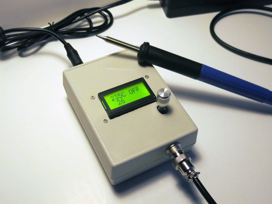
In this project i will show you how to create your own soldering iron controller for amazing Hakko T12 tips on Arduino. This is my first soldering controller for hakko T12 tips.
The major update was performed 04/14/2020:
You have to update your hardware according to the updated schematics if you want use ambient temperature sensor or TILT/REED switch. Or you can continue to use your existing hardware. Please, see the detailed description below.
The Hakko T12 soldering tips are amazing tools for soldering: they heat very fast and can reach very high temperatures in a short period of time. Each tip have a built-in thermo couple to control its temperature very accurately. Also, using appropriate handle, you can replace the tip on the fly in 1 second.
The main features of this controller are:
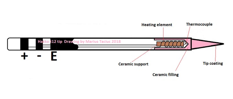
The Hakko T12 soldering tips
The first thing you need to use these tips is a handle. There are a several handles for these tips in the market and I would like to recommend you to order the FX-9501 one. This handle has a light weight, very convenient and has a good quality socket (inside) to plug the tip. You can easily change the tip on the fly if you wish. The tip has 3 wires: "+", "-" and earth ground. The heater is connected consequently with the thermo couple inside the tip, so it required two wires to be connected to the controller only. First problem was the original connector of the handle. It is so rarely used, I could not find the socket for it, so I used the aviation plug GX12-5.
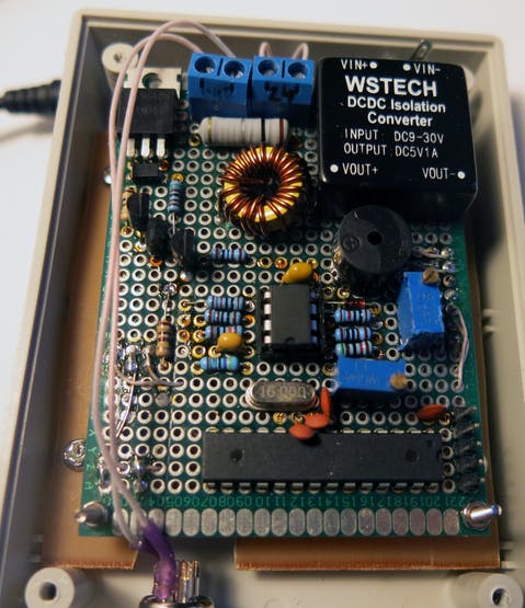
The complete controller schematics is shown on the picture below. The controller is built on the atmega328p-pu micro controller running at 16 MHz. You can use Arduino nano or UNO board if you wish. They are completely compatible. There are some sockets that should be explained in the schematics. SV1 is a serial connector allowing load the sketch to the Arduino. You can use USB to UART converter to program the controller. JP1 is a lcd0802 connector. JP2 & JP3 are actually a single 5-pin aviation plug used to connect soldering iron handle. SV2 connector is used to attach rotary encoder. As you can see on the picture, the DC-DC converter is used to get 5v for the operating amplifier and to power the micro controller. The WSTECH DC-DC isolated converter is implemented. It supplies very stable power for the operating amplifier.
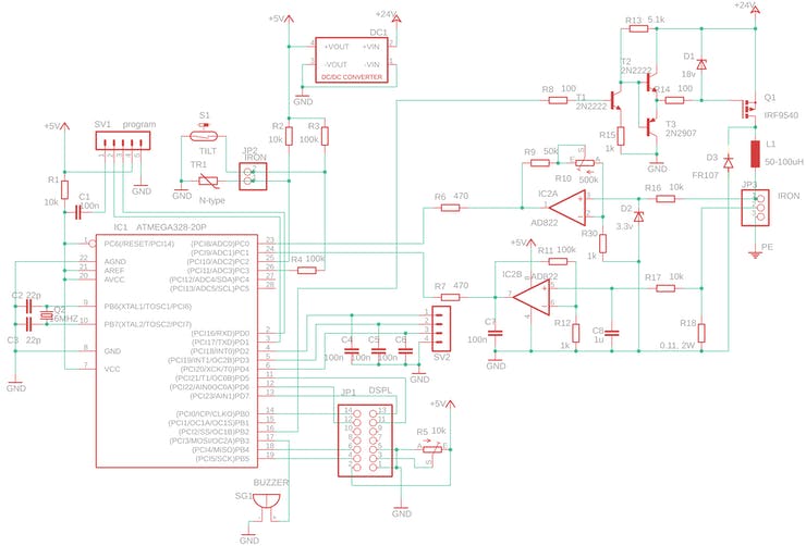
In the controller schematics you can see the potentiometer R10 (500kOhm) that tunes the operation amplifier to get the expected temperature readings at Arduino pin A0. You can use different operating amplifier, you can use different tips so this potentiometer increases the controller flexibility. This potentiometer should be tuned at least once when you created the controller. The main idea is that the controller reads the voltage from the thermo couple through the ADC and gets some integer data in the interval 0-1023 depending of the voltage on pin A0. The near the voltage to 5v the near the readings to the 1023. The potentiometer should be tuned so when the iron temperature become 400 centares, the ADC reading should be about 900.