
 About me
  History
  Let's learn
  Contact us
  Arduino tutorials
 Circuits tutorials
  Robotics tutorials
 Q&A
Q&A Blog
Blog  Arduino
  Circuits
 Robotics
  Modules
  Gadgets
  Printers
  Materials
  3D objects
  3D edit
  Donate
  Reviews
  Advertising


Brushed motors Arduino drone
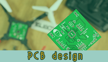
Part 2 - Designed PCB
INTRO part 2
What's up my friends. In a past tutorial we have buid an Arduino based drone using brushless motors. That was a good project. But, uisng brushless motors could get the prject quite expensiv around 8$ for each motor and also for each ESC, so that could get you up to 80$ just for the motors. A cheapper solution is using mini brushed coreless motors and that's what we will do in this tutorial.
To control the DC brushed motors, we will only need a MOSFET for each motor, controlled with PWM signal. The input will be 3.7V from a lipo battery. The PID will be generated using data from and IMU module and the radio receiver will be a NRF24 module once again. So the transmitter will be the same as in the past TRANSMITTER tutorial so make sure you check that out in order to see how to build the transmitter.
Step 1 Part list
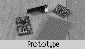
Ok so first of all we will see all the parts we need for this project and why we need each part. There are two ways to make this project. One is using an Arduino pro mini pn a drilled prototyping PCB and all the components or design our own PCB and have it printed by a professional manufacturer.
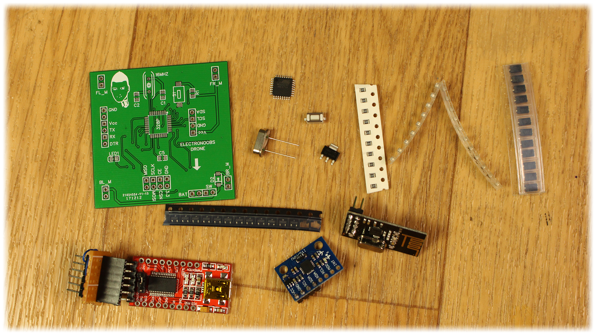
Full part list here
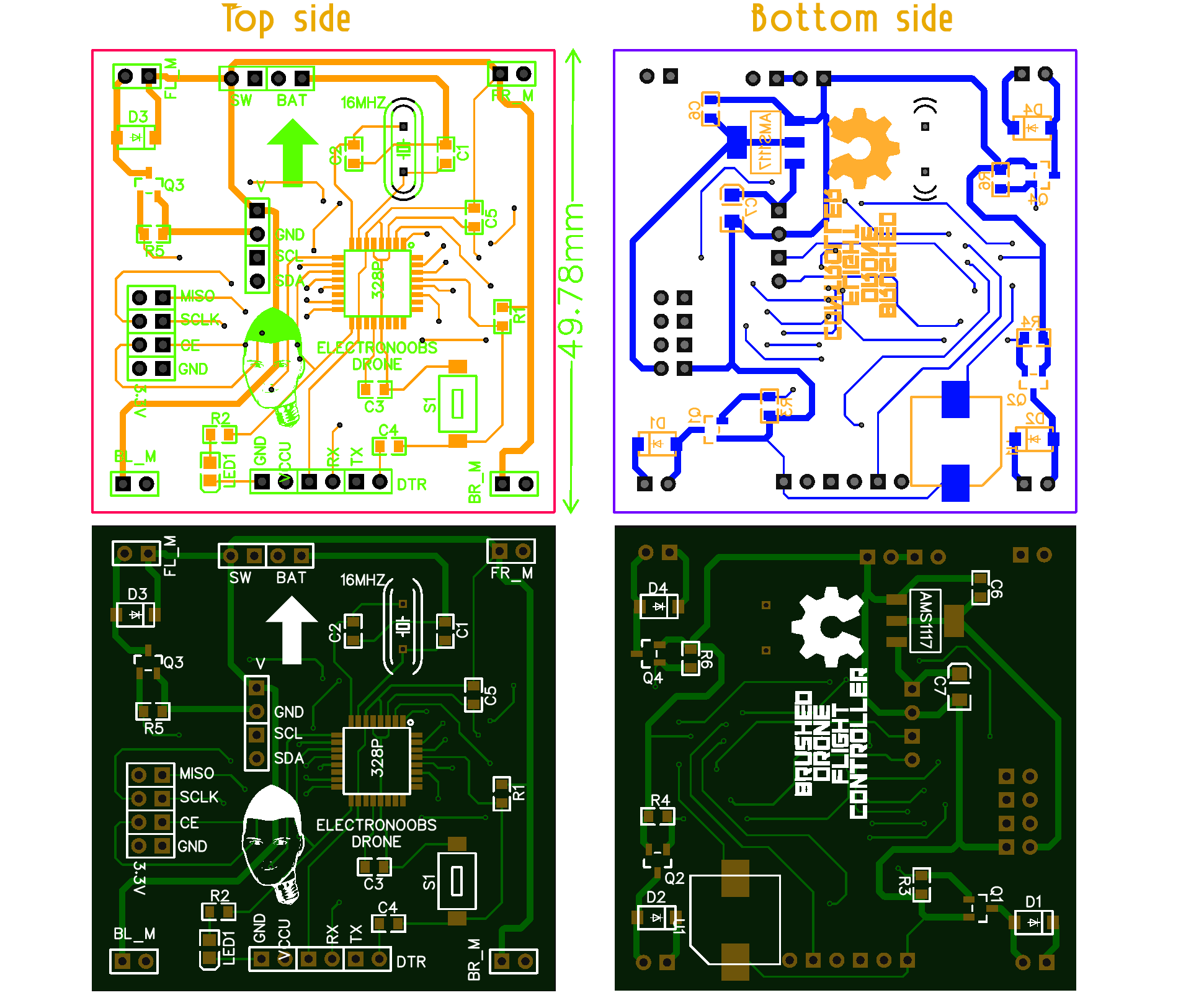
Step 2 The schematic
In the photo below you have the schematic I've used for my board. The board in the photo is not the final version, since the first 4 versions had some errors. But as you can see, we have the 4 MOSFETs, the pins for the IMU, the NRF24 module and all the inputs and outputs that we need. Once again, we haev the 3.3V voltage regulator for the radio module. I' create a new PCB layout and place all the components.

So as you can see in the schematic above, we have the ATmega328p chip. To make it work we have to add the 16MHz crystal oscillator between pins 7 and 8 and also two 22pF capacitors betwenn the crystal and GND to amke it oscillate. We haev to add the 10k pullup to the reset pin. We also have a reset push button, some copuling capacitors, and LED at pin 13 (SCK) and maybe a buzzer.
The transistors are the same, the SI2302. Remember to add the flyback diodes. Let's see the layout.
More about schematic here
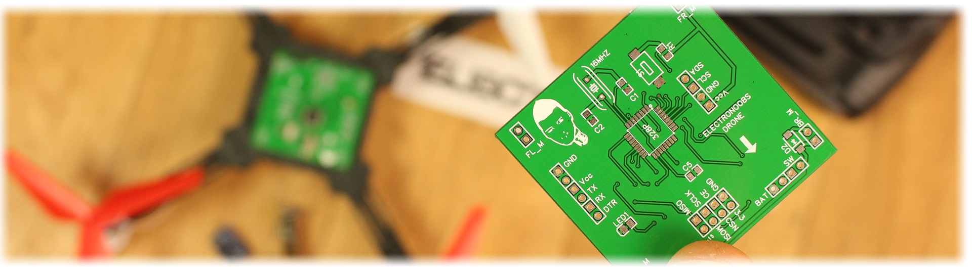
Step 3 The board
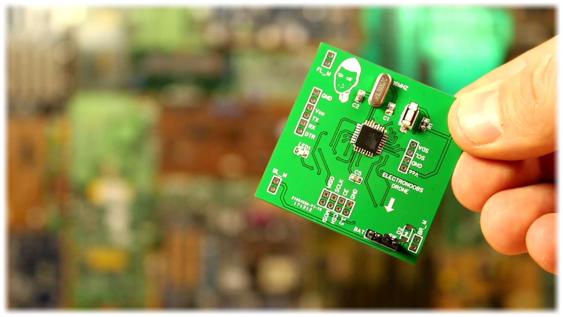
Let's prepare the PCB. I've sent the design to a proffessional manufacturer. I've received the board and all the components. I first solder the smd ATmega328p AU chip in the middle of the board. It might seam tricky but it is easier than it looks. Jsut put a bit of solder on the PCB pads. Place the chip and add a lot of flux. Solder will only stick to the metal pads and pins.
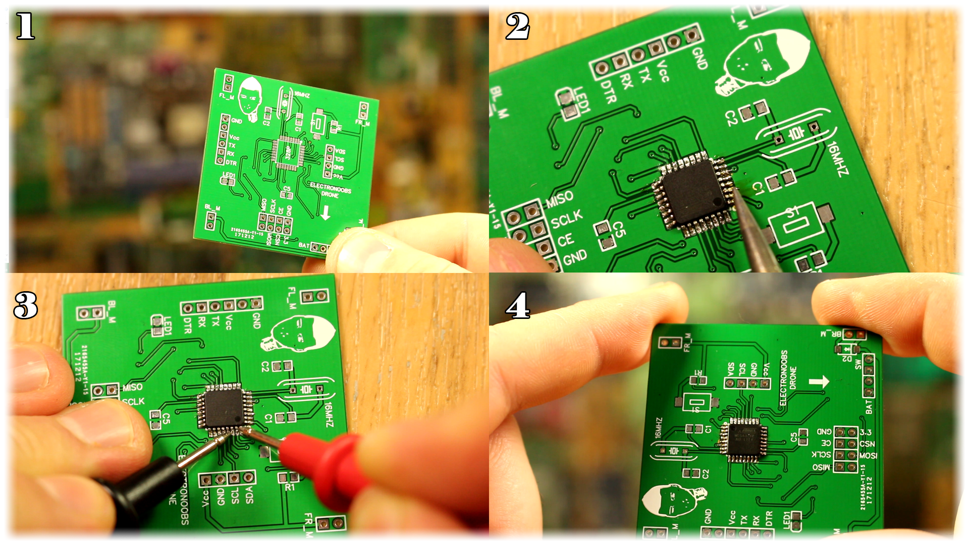
As youc an see above, I solder the smd chip. Once we do that, take your multimeter anc check for short circuits. If everything is ok we keep soldering the components. We add the voltage regulator, the capacitors, the push button and pins.
Step 4 The bootloader
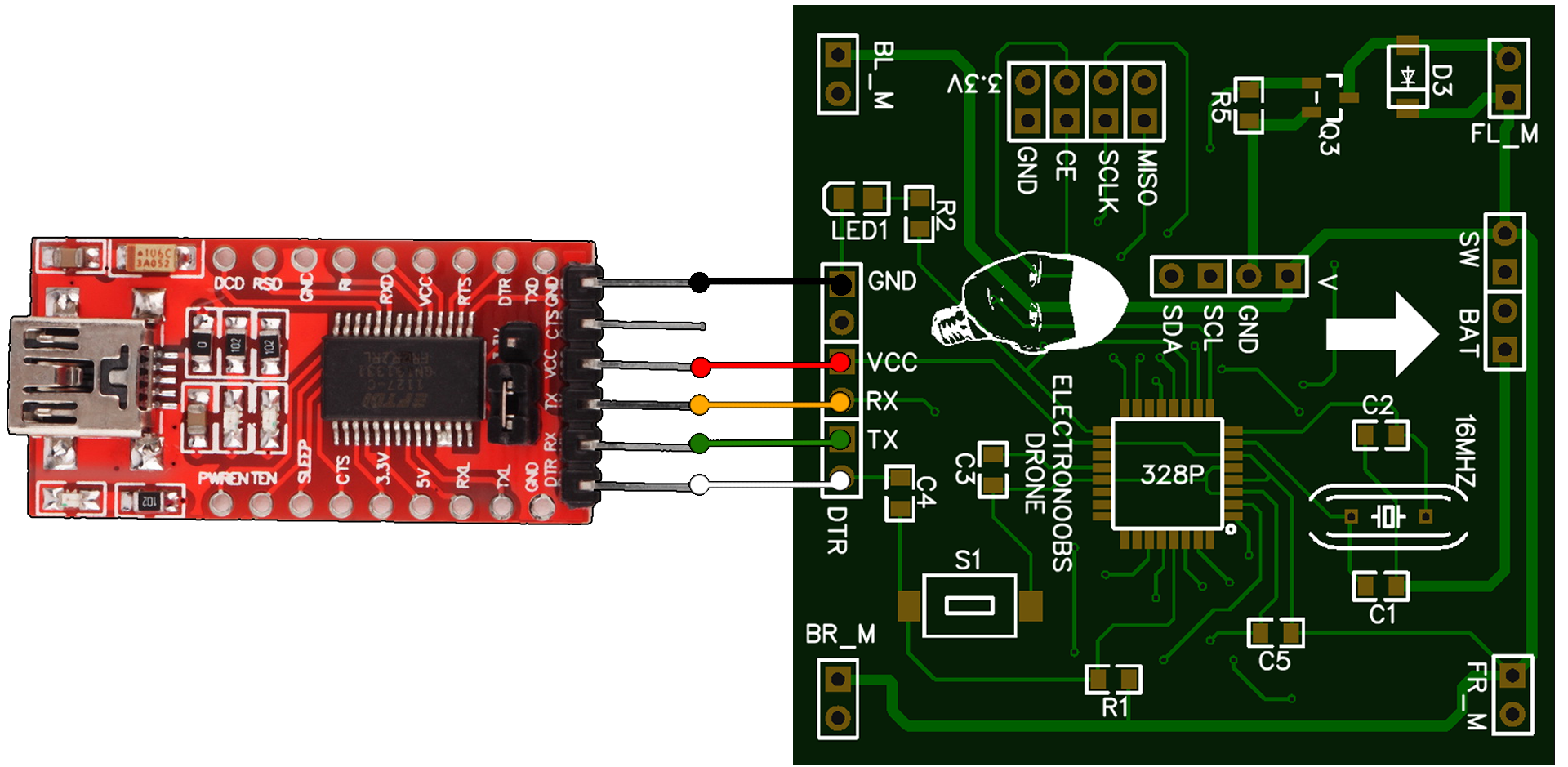
Ok, so the board won't work without a bootloader. For that make the enxt connections between an Arduino NANO and the designed PCB.
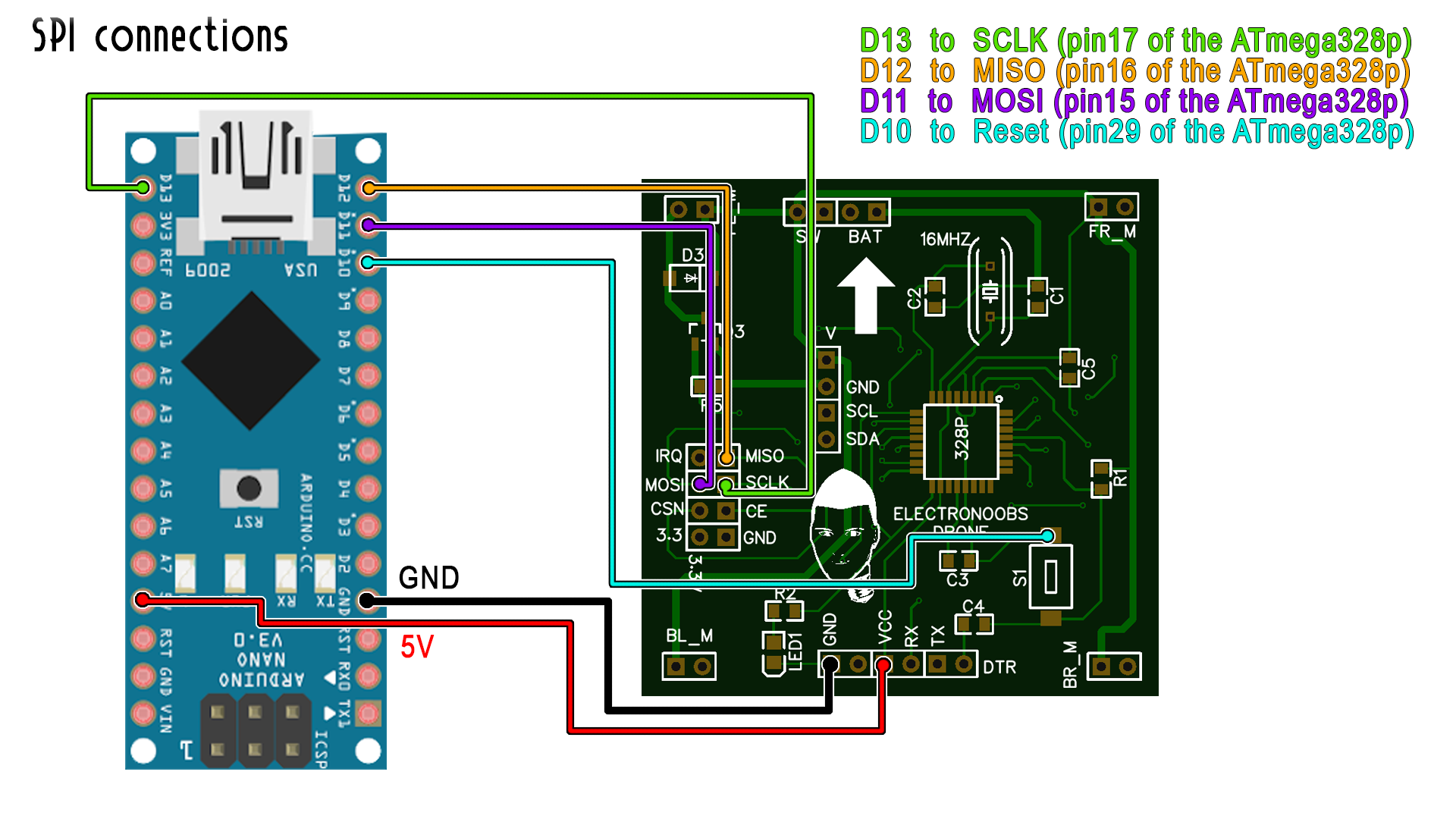
Be careful. The DTR pin has to go to the reset pin on the push button. The final board will haev a separated pad for the DTR pin. Now all the connections are made. Before burnning the bootloader we haev to first upload a code to the arduino.
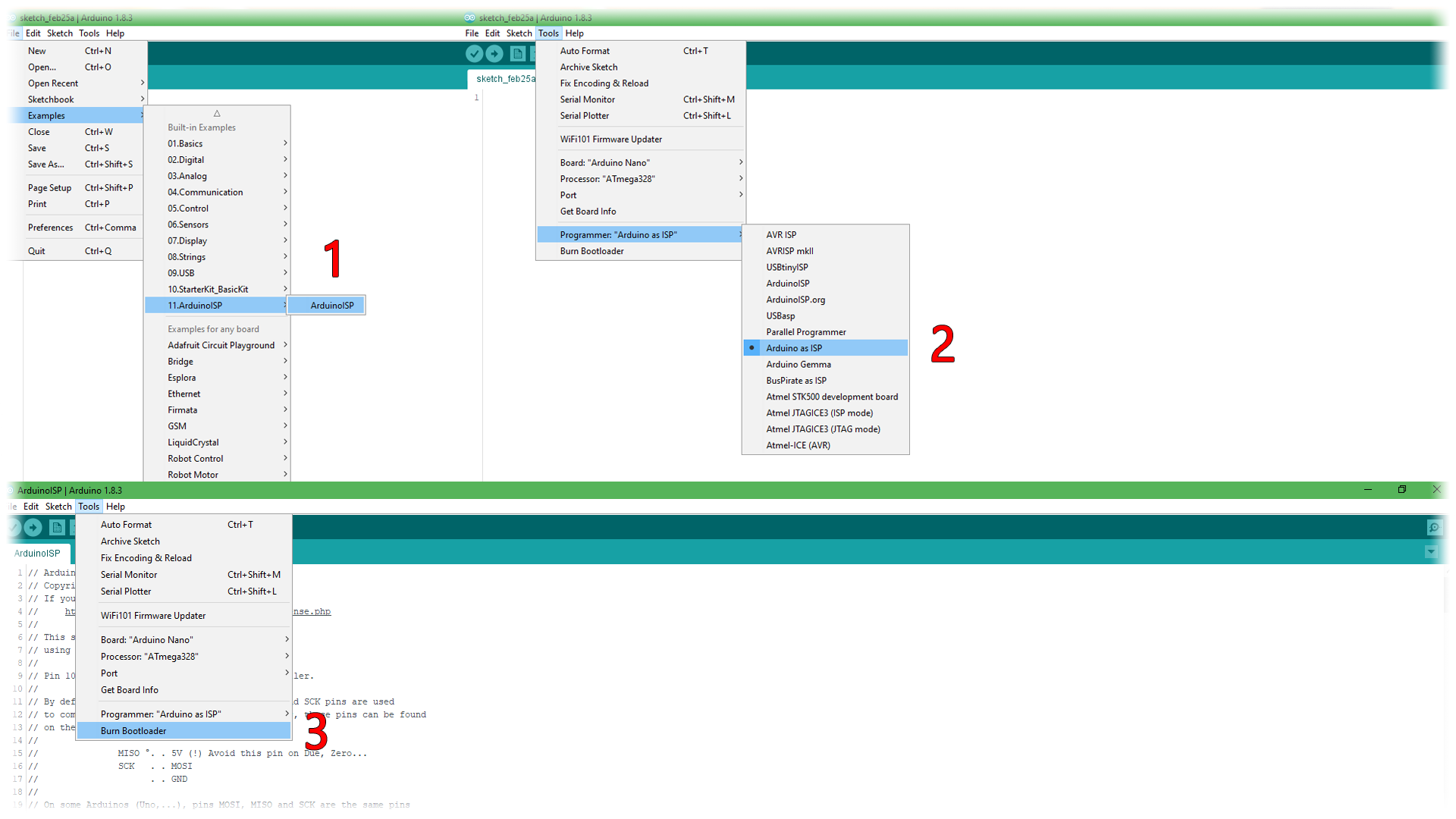
Open Arduino IDE. Go to File, examples, ArduinoISP and open that code. Now connect the Arduino NANO to the USB and select the com. Uplaod the code to the Arduino NANO. Now make sure you ahve the connections above between the Arduino NANO and the PCB. Now go to tools, probrammer and select Arduino as ISP. Now go to tools once again and select burn bootloader.
The LEDs of the Arduino will flash rapidlly. The bootloader is now burned. We can now upload a code to the PCB using an external FTDI programmer. Make the connections below between the module and the baord and remember to change back the programmer to Arduino mkII.
Now open a blink example adn change the blink LED to pin 13 (LED pin of our board), connect the FTDi module to the PC and upload the code to the board. The LED on pin 13 should blink each 1 seconds.
Testing the MOSFETs
So, the board works. We can now solder the MOSFETS and diodes. Solder each motor to the PCB. Once we do taht we should uplaod the next small example code to test if the motors will spin. So copy the code, connect the FDTI odule and upload. If the motors are spinning, now we can solder the NRF24 and the IMU modules and test those out again using the codes before on PART 1.
//We define the pins for the mootrs
int front_left  = 3;
int back_left   = 5;
int front_right = 6;
int back_right  = 9;

void setup() {
  //Define the pins as outputs
  pinMode(front_left,OUTPUT);
  pinMode(back_left,OUTPUT);
  pinMode(front_right,OUTPUT);
  pinMode(back_right,OUTPUT);
  }

void loop() {
 analogWrite(front_left,50);
 analogWrite(back_left,50);
 analogWrite(front_right,50);
 analogWrite(back_right,50);
 delay(10);
 }
Testing the IMU and NRF24
Now solder the modules. Below you ahve two examples for testing the IMU and NRF24. First upload the IMU code and open serial monitor. Move the boar adn look how the angle is cahnging. If taht works, now uplaod the NRF example receiver code. Opens erial monitor, power up the transmitter and move the joysticks. You should receive the values on the serial monitor.
If everything works ok, is time to upload the code. The body is the same as in PART1. Solder th motors, put the boar in the center of the drone and lets upload the Multiwii code.