
 About me
  History
  Let's learn
  Contact us
  Arduino tutorials
 Circuits tutorials
  Robotics tutorials
 Q&A
Q&A Blog
Blog  Arduino
  Circuits
 Robotics
  Modules
  Gadgets
  Printers
  Materials
  3D objects
  3D edit
  Donate
  Reviews
  Advertising


Brushed motors Arduino drone
Ok, now we have all the modules soldered in place. Is time to add the 4 msofets. Each with a pulldown of 10K and also a diode ad the output. We put some solder to the holes where we will connect the DC motors. We add the pins for the battery input.
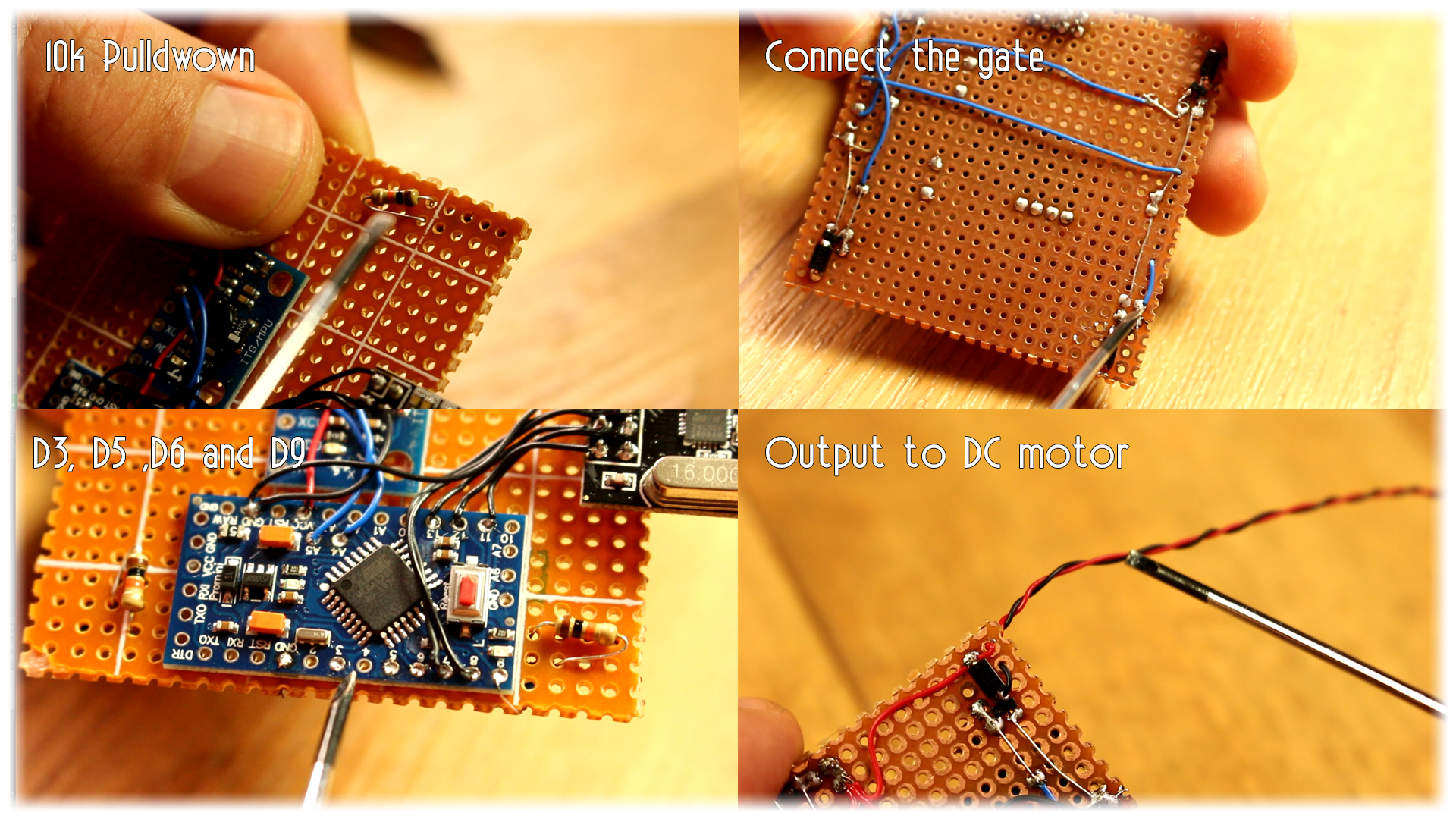
Before I solder the DC motors to the board, I applt 3V to each in order to see if they spin in the corredt direction and which will be the positive and negative wire. Then I solder the DC motor between 3.7V from the batter and the drain of the n-ch MOSFET.
Now I uplaod the next small example code to thest if the motors are spinning at a low speed. Uplaod the code and connect the battery and let's see.
//We define the pins for the mootrs
int front_left  = 3;
int back_left   = 5;
int front_right = 6;
int back_right  = 9;

void setup() {
  //Define the pins as outputs
  pinMode(front_left,OUTPUT);
  pinMode(back_left,OUTPUT);
  pinMode(front_right,OUTPUT);
  pinMode(back_right,OUTPUT);
  }

void loop() {
 analogWrite(front_left,50);
 analogWrite(back_left,50);
 analogWrite(front_right,50);
 analogWrite(back_right,50);
 delay(10);
 }
Step 6 The code
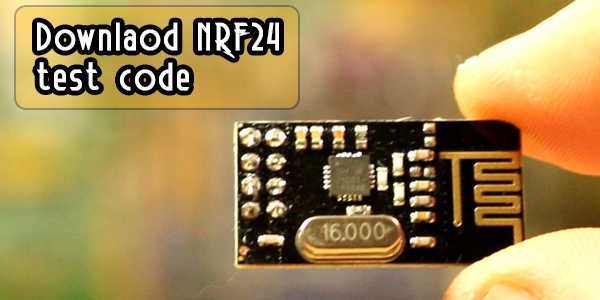
Now we know that the motors are working. We should also test if the Radio connection and the MPU6050 are working well. For taht you ahve two example codes below. Upload first the MPU6050 code adn once uploaded, open the serial monitor and move the board around. The angle should change. If it works, test the radio connection.
upload the radio test code and power up the radio transmitter. Open serial monitor adn move the joysticks. The value for each cahnnel should change acording to the position of the joystick.
Now we know that each part works ok. The code that we will use first is a MultiWii platform as in the past tutorial on Arduino based drone for quadX drone. Ina future part we will make our own code but that doesn't work quite well yet, sorry.
Go to the link below and donwload that zip file. Inside you will have the MultiWii Arduino code and the Multiwii Java platform for 32 and 64 bits.
Connect the FTDI module to to the Arduino pro mini, open the code, select Arduino pro mini as programmer and upload the code. Now with the FTDI module connected, open the Java Multiwii Platform and let's see if everything is ok.
Download multiwii here:
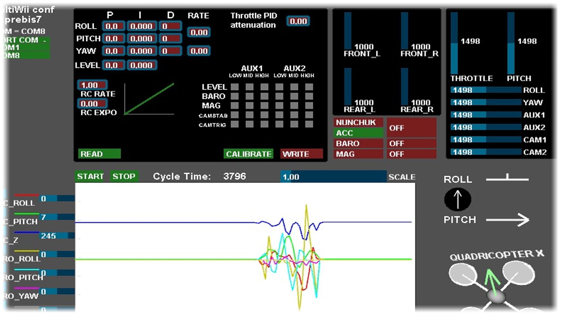
With the code uploaded, the FTDI connected and the Multiwii platform on, power the transmitter and chech if you can receive data for throttle, yaw, pithc and roll. Also the extra 2 AUX channel. To power the motors put throttle to minimum and yaw to maximum for 3 seconds. Now we can fly.