Android bluetooth Arduino data receive
3.0 Receive data & detect object
In this part of the tutorial we will use the HC-sr04 ultrasonic sensor to detect distance. If the distance is below 20xm we send the character "d" from detected. If not we send "n" for nothing. In the App we detect the received character and depending of its value we change a label color and text to green adn "DETECTED" or red and "NOTHING". So let's atart.

Downlaod this App here
3.1 The schematic
The schematic is a bit different since now we have the sensor HC-sr04 connected. In the next photo below you have the schematic that you should mount for this simple part using the Arduino UNO. The sensor is connected to 5V and GND. The trigger pin is digital pin 3 and the echo pin is digital pin 2. The Bluetooth module is the HC06 and it has a UART comunication so it will use the Tx and Rx pins.
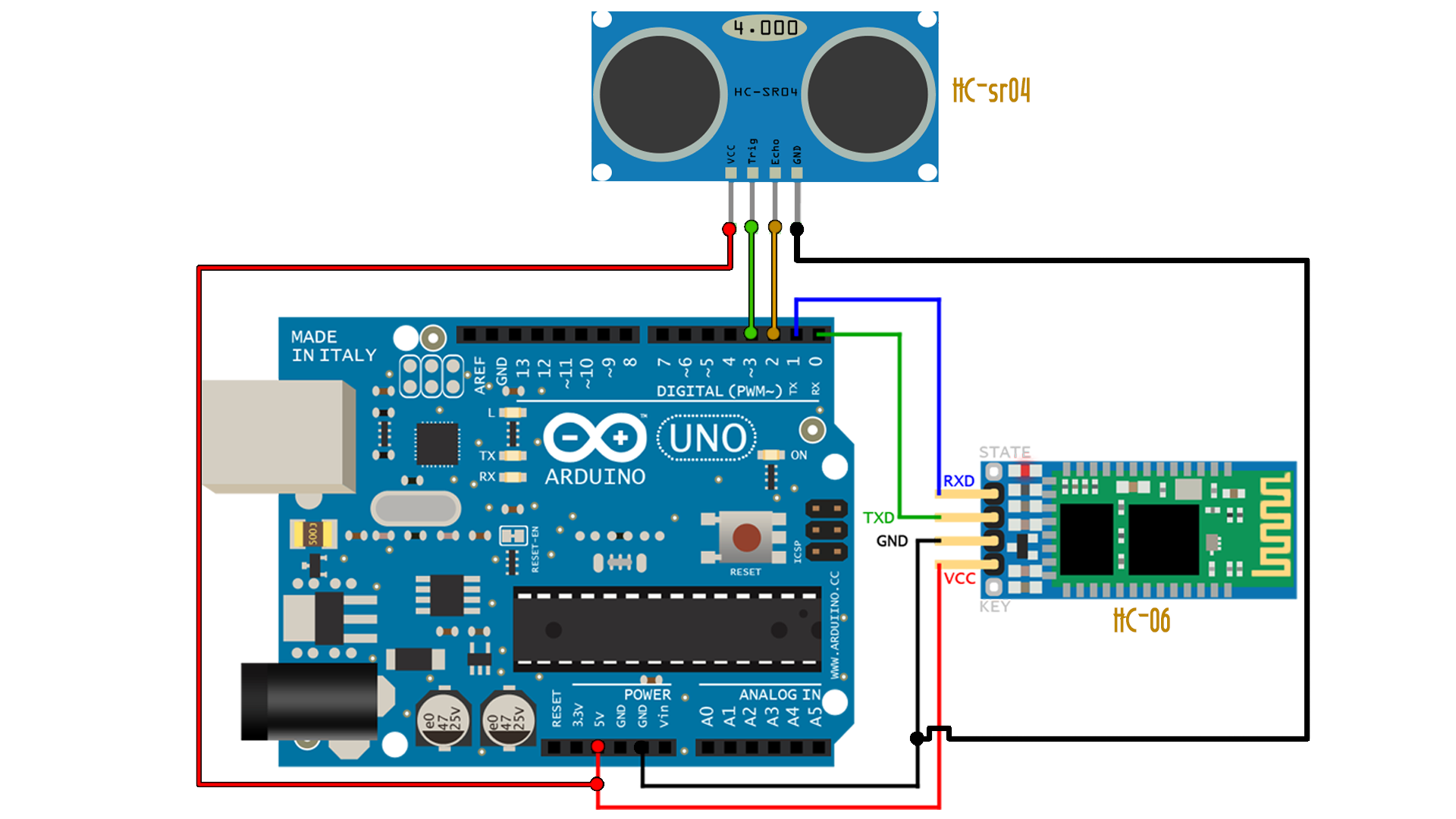
Ok, now we have the schematic that will detect any object in front of the sensor. Let's take a look over the code now.
3.2 The code
Ok guys, the first thing is to define the duration of the pulse and the cm variables and the trigger and echo pins as digital pin D3 and D2. In the void Setup we start a serial comunication with a baud rate of 9600 bauds since the HC06 bluetooth modules works at that speed by default and also define the pins as INPUT for the echo and OUTPUT for the trigger.
The code is simple. We send a pulse of around 10 microseconds with the trigger pin. The sound wave will hit an object and will bounce and get back to the sensor. If we count the time between when the pulse was sent and it get back to the sensor and divide that by 2 we get the time that the pulse needs to travel the distance. We know the speed of sound, so if we divide that time by the speed of time in us, we get the distance since the distance is speed multiply by time.
/* Electronoobs Bluetooth data receive with
 * Android and Arduino. Small example.
 * Remember to disconnect the Rx and Tx pins of the HC-06 when
 * uploading the code
 *
 * Subscribe: http://www.youtube.com/c/ELECTRONOOBS
 * Tutorial: http://www.electronoobs.com/eng_arduino_tut20_2.php
 */
const int trigPin = 3; const int echoPin = 2; long duration, cm;

void setup() {
  // initialize serial communication with HC-06:
  Serial.begin(9600);  pinMode(trigPin, OUTPUT);  pinMode(echoPin, INPUT);
}

void loop()
{
  // The sensor is triggered by a HIGH pulse of 10 or more microseconds. // Give a short LOW pulse beforehand to ensure a clean HIGH pulse:
  digitalWrite(trigPin, LOW);
  delayMicroseconds(2);
  digitalWrite(trigPin, HIGH);
  delayMicroseconds(10);
  digitalWrite(trigPin, LOW);
  // Read the signal from the sensor: a HIGH pulse whose  // duration is the time (in microseconds) from the sending  // of the ping to the reception of its echo off of an object.
  duration = pulseIn(echoPin, HIGH);
  // convert the time into a distance
  cm = (duration/2)/29.1;
  if(cm < 20)
  {
    Serial.print("d"); delay(400);
  }
  else
  {
    Serial.print("n"); delay(400);
  }
}
As you can see above, if the distance in cm is below 20, se use the
3.3 The App
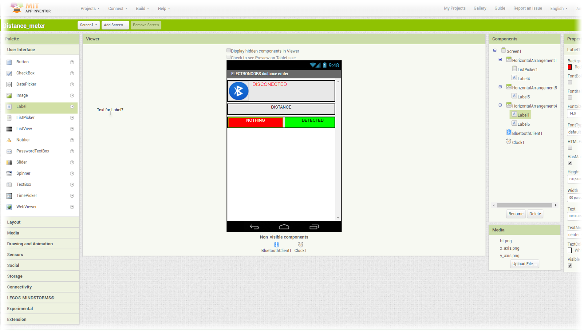
The App is a bit different than the previous as you can see below. We still have the connection part but next we have two labels. One will print "DETECTED" and the other one "NOTHING" with green or red. So we add a new horizontal arrangement and inside we add two labels with 50% width each as you can see below.
3.3.2 The App code Blocks
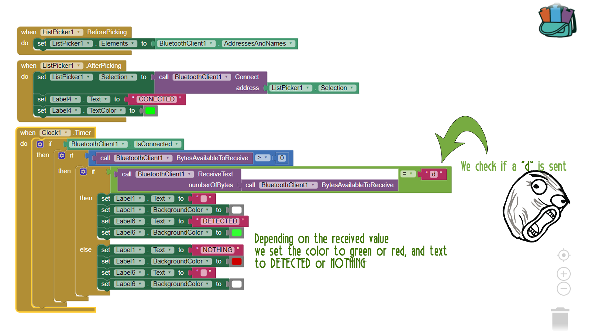
The time and connection code in this case is the same. We connect using the list piker. Once connected we have to mount the code blocks below. Once again we chec if there is a connection and if there are bytes to receive. If yes we then check the value that we receive. If the value is a "d" then we set label 6 to green and the text of that label to DETECTED. If not we set label 6 to white and a blank space, and we set label 1 to red and the text NOTHING. That's it.
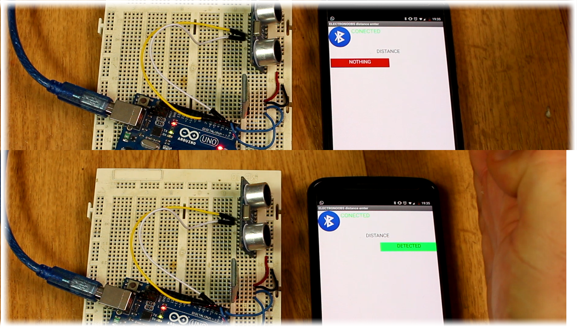
Now save the App, install it to the smartphone and open it. Once the code is uploaded to the Arduino, connect the sensor and the Bluetooth module. Open the App and connect to HC06. Now as you can see below, each time I place my hand in front of the sensor I get the message DETECTED. Nice and simple right?
Quite easy right? You could improve the App any way you want. This was just a small example of what you could do and how to use the

 About me
  History
  Let's learn
  Contact us
  Arduino tutorials
 Circuits tutorials
  Robotics tutorials
 Q&A
Q&A Blog
Blog  Arduino
  Circuits
 Robotics
  Modules
  Gadgets
  Printers
  Materials
  3D objects
  3D edit
  Donate
  Reviews
  Advertising
