Not that it is ready, I wanted to test it so I’ve connected a small brushless motor one at the output. But as you can see in the video on this thermal camera, some mosfets were getting hot. That’s because the P MOSFET I’ve used on the PCB design has the source and drain pads reversed. That’s the error I mentioned at the beginning. (Don't worry, the error was fixed on the GERBERs you download) That’s why, finally I’ve soldered 3 of the MSOFETs like you can see in the video. It looks ugly but at least I can test it. Having this thermal camera helped me a lot to find out which component was failing.
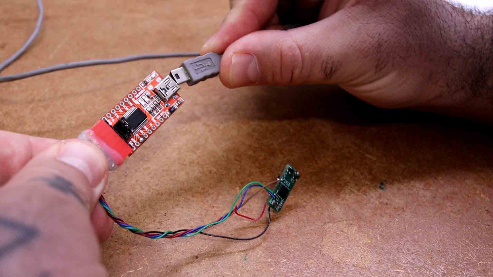
I use the FTDI programmer to upload the code. If you check the code, you will see that we use PC INT interruptions on pin D8 to read the PWM input. Then, this is the comparator interrupt on pin D6. That’s where the feedback zero cross is connected as you can see in the schematic. Depending on the feedback, we change to the next part of the sequence. We have these 6 steps of that sequence. And depending on the step, we activate the pins that go to the MOSFET bridge, and that’s it. I upload it and I do some tests.
The code has 3 extra files so make sure you downlaod the entire ZIP file instead of just coping the code from below...
/********************************************************************************************************
 *  Title: ELECTRONOOBS open source electronic speed controller.
 * Date: 22/03/2024
 * Version: 1.5
 * Author: http://electronoobs.com
 * Based on tutorial: https://www.electronoobs.com/eng_arduino_tut196.php

 * This is a sensorless ESC based on Arduino with the ATmega328 chip. It uses BEMF
 * with the internal comparator of the ATmega328 on pin D6 to detect the rotor position.
 * The speed control is made by a PWM signal. Feel free to change it and improve
 * it however you want
 * Subscribe: http://youtube.com/c/ELECTRONOOBS
********************************************************************************************************/

#include "EEPROMAnything.h"   //A library I've made to store more than just one byte to the EEPROM
#include "Variables.h"        //Here I store all the variables
#include "Beeps.h"            //A simple code to create beeps uisng the motor coils...

void setup() {


  //Our pins for the MOSFETs are 2,3,4 and 9,10,11
  DDRD  |= B00011100;           //Configure pins 2, 3 and 4 as outputs CL, BL and AL
  PORTD  = B00000000;           //Pins 0 to 7 set to LOW
  DDRB  |= B00001110;           //Configure pins 9, 10 and 11 as outputs
  PORTB  &= B00110001;          //D9, D10 and D11 to LOW
  // Timer1
  TCCR1A = 0;
  TCCR1B = 0x01;
  // Timer2
  TCCR2A = 0;
  TCCR2B = 0x01;
  // Comparator on pin D6
  ACSR   = 0x10;                // Clear flag comparator interrupt
  //Set D8 (PWM in) to trigger interrupt (we use this to read PWM input)
  PCICR |= (1 << PCIE0);        //enable PCMSK0 scan
  PCMSK0 |= (1 << PCINT0);      //Set pin D8 trigger an interrupt on state change.

  delay(50);

  if(PWM_INPUT > PWM_IN_MIN + 115)
  {
     ESC_MODE_ON = false;       //Motor rotation is OFF till the config mode is done
    while(!PWM_RANGE_SET)
    {
      currentMillis = millis();
      if(currentMillis - previousMillis >= 500)
      {
        OCR1A = beeping_PWM_VALUE;
        previousMillis += 500;
        TCCR2A =  0;            //OC2A - D11 normal port.
        TCCR1A =  0;            // OC1A and OC1B normal port
        beep_1KHZ(100);
      }
      if(PWM_INPUT > MAX_PWM_TO_STORE)
      {
        MAX_PWM_TO_STORE = PWM_INPUT;
      }

      if(PWM_INPUT < 1200)
      {
        if(pwm_set_counter > 1000)
        {
          MIN_PWM_TO_STORE = PWM_INPUT;
          EEPROM_writeAnything(PWM_IN_MIN_ADRESS, MIN_PWM_TO_STORE);
          EEPROM_writeAnything(PWM_IN_MAX_ADRESS, MAX_PWM_TO_STORE);
          ESC_MODE_ON = true;
          PWM_RANGE_SET = true;
          int y = 0;
          TCCR2A =  0;            //OC2A - D11 normal port.
          TCCR1A =  0;            // OC1A and OC1B normal port
          beep_1KHZ(400);
          delay(200);

          TCCR2A =  0;            //OC2A - D11 normal port.
          TCCR1A =  0;            // OC1A and OC1B normal port

          beep_1KHZ(100);
          delay(100);
          beep_2KHZ(100);
          delay(100);
          beep_3KHZ(100);
          delay(100);


        }
        pwm_set_counter = pwm_set_counter + 1;
        delay(1);
      }
      else
      {
        pwm_set_counter = 0;
      }
    }//end of !PWM_RANGE_SET
  }

  /*If the range is below PWM_IN_MIN+115us then we start the code*/
  else
  {
    OCR1A = beeping_PWM_VALUE;
    ESC_MODE_ON = true;
    int x = 0;
    TCCR2A =  0;            //OC2A - D11 normal port.
    TCCR1A =  0;            // OC1A and OC1B normal port
    beep_1KHZ(400);
    delay(200);

    TCCR2A =  0;            //OC2A - D11 normal port.
    TCCR1A =  0;            // OC1A and OC1B normal port

    beep_1KHZ(100);
    delay(100);
    beep_2KHZ(100);
    delay(100);
    beep_3KHZ(100);
    delay(100);

  }

//Save new range to the EEPROM
EEPROM_readAnything(PWM_IN_MIN_ADRESS, PWM_IN_MIN);
EEPROM_readAnything(PWM_IN_MAX_ADRESS, PWM_IN_MAX);
}//End of setup loop


// Interruption vector for the Analog comparator
ISR (ANALOG_COMP_vect) {
  for(i = 0; i < 10; i++) {           //We check the comparator 10 times just to be sure
    if(sequence_step & 1)             //If step = odd (0001, 0011, 0101) 1, 3 or 5
    {
      if(!(ACSR & B00100000)) i -= 1; //!B00100000 -> B11011111 ACO = 0 (Analog Comparator Output = 0)
    }
    else                              //else if step is 0, 2 or 4
    {
      if((ACSR & B00100000))  i -= 1; //else if B00100000 -> B11011111 ACO = 1 (Analog Comparator Output = 1)
    }
  }
  set_next_step();                    //set the next step of the sequence
  sequence_step++;                    //increment step by 1, next part of the sequence of 6
  sequence_step %= 6;                 //If step > 5 (equal to 6) then step = 0 and start over
}


//Switch to next step functions
void set_next_step(){
  switch(sequence_step){
    case 0:
      AH_BL();
      BEMF_C_RISING();
      break;
    case 1:
      AH_CL();
      BEMF_B_FALLING();
      break;
    case 2:
      BH_CL();
      BEMF_A_RISING();
      break;
    case 3:
      BH_AL();
      BEMF_C_FALLING();
      break;
    case 4:
      CH_AL();
      BEMF_B_RISING();
      break;
    case 5:
      CH_BL();
      BEMF_A_FALLING();
      break;
  }
}//end of set_next_step


//main loop
void loop() {
  /*if PWM input is higher than PWM_IN_MIN + 115 we start the motor*/
  if(PWM_INPUT > (PWM_IN_MIN + 115) && ESC_MODE_ON)
  {
    MOTOR_SPINNING = true;
    full_stop = false;
    motor_off_counter = 0;
  }
  //////////////////////////Motor is rotating////////////////////////
  if(MOTOR_SPINNING)
  {
    SET_PWM(PWM_value);     // Setup starting PWM with duty cycle = PWM_START_DUTY
    i = 2000;
    // Motor start
    while(i > 500) {
      delayMicroseconds(i);
      set_next_step();
      sequence_step++;
      sequence_step %= 6;
      i = i - 10;
    }
    motor_speed = PWM_value;
    set_next_step();
    ACSR |= 0x08;                    // Enable analog comparator interrupt
    while(MOTOR_SPINNING)
    {
      PWM_INPUT = constrain(PWM_INPUT,PWM_IN_MIN,PWM_IN_MAX);
      motor_speed = map(PWM_INPUT,PWM_IN_MIN,PWM_IN_MAX,PWM_min_value,PWM_max_value);
      SET_PWM(motor_speed);
      if(PWM_INPUT < (PWM_IN_MIN + 30))
      {
        if(motor_off_counter > 10000)
        {
          MOTOR_SPINNING = false;
          motor_off_counter = 0;
          PORTD = B00000000;      //Set D0-D7 to LOW
          TCCR1A =  0;            //OC1A - D9 compare match noninverting mode, downcounting ,PWM 8-bit
          TCCR2A =  0;            //OC1A - D9 compare match noninverting mode, downcounting ,PWM 8-bit
          previousMillis = millis();
        }
        motor_off_counter = motor_off_counter + 1;
      }
    }
  }//end of if MOTOR_SPINNING


  //////////////////////////Motor STOP////////////////////////
  if(!MOTOR_SPINNING)
  {
    unsigned long currentMillis = millis();
    if(currentMillis - previousMillis >= 4000 && !full_stop)
    {
      previousMillis += 4000;
      full_stop = true;
    }
    if(full_stop)
    {
      if(currentMillis - previousMillis >= 2000)
      {
        previousMillis += 2000;
        ACSR   = 0x10;            // Disable and clear (flag bit) analog comparator interrupt
        TCCR2A =  0;
        TCCR1A =  0;
        PORTD  = 0x00;            //pins 0 to 7 set to LOW //stop everything
        PORTB  &= 0x31;           //B00110001    D9, D10 and D11 to LOW
        OCR1A = beeping_PWM_VALUE;
        beep_1KHZ(100);     //make a 100 ms beep
      }
    }
    else
    {
      ACSR   = 0x10;            // Disable and clear (flag bit) analog comparator interrupt
      TCCR2A =  0;
      TCCR1A =  0;
      PORTD  = B00000000;            //pins 0 to 7 set to LOW //stop everything
      PORTB  = B00000000;           //B00110001    D9, D10 and D11 to LOW
    }
  }//end of if !MOTOR_SPINNING
}//end of void loop


/*On each step we know that the next 0 cross will be rising or falling and if it will be
on coil A, B or C. With these funcstions we select that according to the step of the sequence*/
void BEMF_A_RISING(){
  ADCSRA = (0 << ADEN);     // Disable the ADC module
  ADCSRB = (1 << ACME);     // MUX select for negative input of comparator
  ADMUX = 2;                // Select A2 as comparator negative input
  ACSR |= 0x03;             // Set interrupt on rising edge*/
}
void BEMF_A_FALLING(){
  ADCSRA = (0 << ADEN);     // Disable the ADC module
  ADCSRB = (1 << ACME);     // MUX select for negative input of comparator
  ADMUX = 2;                // Select A2 as comparator negative input
  ACSR &= ~0x01;            // Set interrupt on falling edge*/
}
void BEMF_B_RISING(){
  ADCSRA = (0 << ADEN);     // Disable the ADC module
  ADCSRB = (1 << ACME);     // MUX select for negative input of comparator
  ADMUX = 1;                // Select A1 as comparator negative input
  ACSR |= 0x03;             // Set interrupt on rising edge
}
void BEMF_B_FALLING(){
  ADCSRA = (0 << ADEN);     // Disable the ADC module
  ADCSRB = (1 << ACME);     // MUX select for negative input of comparator
  ADMUX = 1;                // Select A1 as comparator negative input
  ACSR &= ~0x01;            // Set interrupt on falling edge*/
}
void BEMF_C_RISING(){
  ADCSRA = (0 << ADEN);     // Disable the ADC module
  ADCSRB = (1 << ACME);     // MUX select for negative input of comparator
  ADMUX = 0;                // Select A0 as comparator negative input
  ACSR |= 0x03;             // Set interrupt on rising edge
}
void BEMF_C_FALLING(){
  ADCSRA = (0 << ADEN);     // Disable the ADC module
  ADCSRB = (1 << ACME);     // MUX select for negative input of comparator
  ADMUX = 0;                // Select A0 as comparator negative input
  ACSR &= ~0x01;            // Set interrupt on falling edge*/
}


/*On each step we change the digital pins to be HIGH or LOW or to be PWM or no-PWM
depending on which step of the sequence we are*/
//D9 PWM and D3 HIGH.
void AH_BL(){
  PORTD = B00001000;      //Set D3 (BL) to HIGH and the rest to LOW
  TCCR2A =  0;            //OC2A - D11 normal port.
  TCCR1A =  0x81;         //OC1A - D9 (AH) compare match noninverting mode, downcounting ,PWM 8-bit
}
//D9 PWM and D2 HIGH
void AH_CL(){
  PORTD = B00000100;      //Set D2 (CL) to HIGH and the rest to LOW
  TCCR2A =  0;            //OC2A - D11 normal port.
  TCCR1A =  0x81;         //OC1A - D9 (AH) compare match noninverting mode, downcounting ,PWM 8-bit
}
//D10 PWM and D2 HIGH
void BH_CL(){
  PORTD = B00000100;      //Set D2 (CL) to HIGH and the rest to LOW
  TCCR2A =  0;            //OC2A - D11 normal port.
  TCCR1A =  0x21;         //OC1B - D10 (BH) compare match noninverting mode, downcounting ,PWM 8-bit
}
//D10 PWM and D4 HIGH
void BH_AL(){
  PORTD = B00010000;      //Set D4 (AL) to HIGH and the rest to LOW
  TCCR2A =  0;            //OC2A - D11 normal port.
  TCCR1A =  0x21;         //OC1B - D10 (BH) compare match noninverting mode, downcounting ,PWM 8-bit
}
//D11 PWM and D4 HIGH
void CH_AL(){
  PORTD = B00010000;      //Set D4 (AL) to HIGH and the rest to LOW
  TCCR1A =  0;            // OC1A and OC1B normal port
  TCCR2A =  0x81;         // OC2A - D11 (CH) compare match noninverting mode, downcounting ,PWM 8-bit
}
//D11 PWM and D3 HIGH
void CH_BL(){
  PORTD = B00001000;      //Set D3 (BL) to HIGH and the rest to LOW
  TCCR1A =  0;            // OC1A and OC1B normal port
  TCCR2A =  0x81;         // OC2A - D11 (CH) compare match noninverting mode, downcounting ,PWM 8-bit
}


/*This function will only change the PWM values according to the received width_value
that is given by the PWM read on pin D8*/
void SET_PWM(byte width_value){
  //We keep the range of PWM between min and max (8 bit value)
  if(width_value < PWM_min_value)    width_value  = PWM_min_value;
  if(width_value > PWM_max_value)    width_value  = PWM_max_value;
  OCR1A  = width_value;                   // Set pin 9  PWM duty cycle
  OCR1B  = width_value;                   // Set pin 10 PWM duty cycle
  OCR2A  = width_value;                   // Set pin 11 PWM duty cycle
}


/*This is the interruption routine on pin change
in this case for digital pin D8 which is the PWM input*/
ISR(PCINT0_vect){
  //First we take the current count value in micro seconds using the micros() function
  current_count = micros();
  ///////////////////////////////////////Channel 1
  if(PINB & B00000001){                              //We make an AND with the pin state register, We verify if pin 8 is HIGH???
    if(last_PWM_state == 0){                         //If the last state was 0, then we have a state change...
      last_PWM_state = 1;                            //Store the current state into the last state for the next loop
      counter_1 = current_count;                     //Set counter_1 to current value.
    }
  }
  else if(last_PWM_state == 1){                      //If pin 8 is LOW and the last state was HIGH then we have a state change
    last_PWM_state = 0;                              //Store the current state into the last state for the next loop
    PWM_INPUT = current_count - counter_1;           //We make the time difference. PWM_INPUT is current_time - counter_1 in micro-seconds.
  }
}