Using this board you could learn how to make each part of my Arduino based multimeter from previous episodes. You have a step for each block for measuring voltage, resistance, inductance, capacitance and current.
Obviouslly, you could make a prototype on a homemade PCB if you want. But is better to use my PCB made to be very easy to assemble. So get the GERBER files and order the PCBs at PCBWAY.com. for example. Once you have the PCBs, all you need are the modules for the ADC, current and the display.
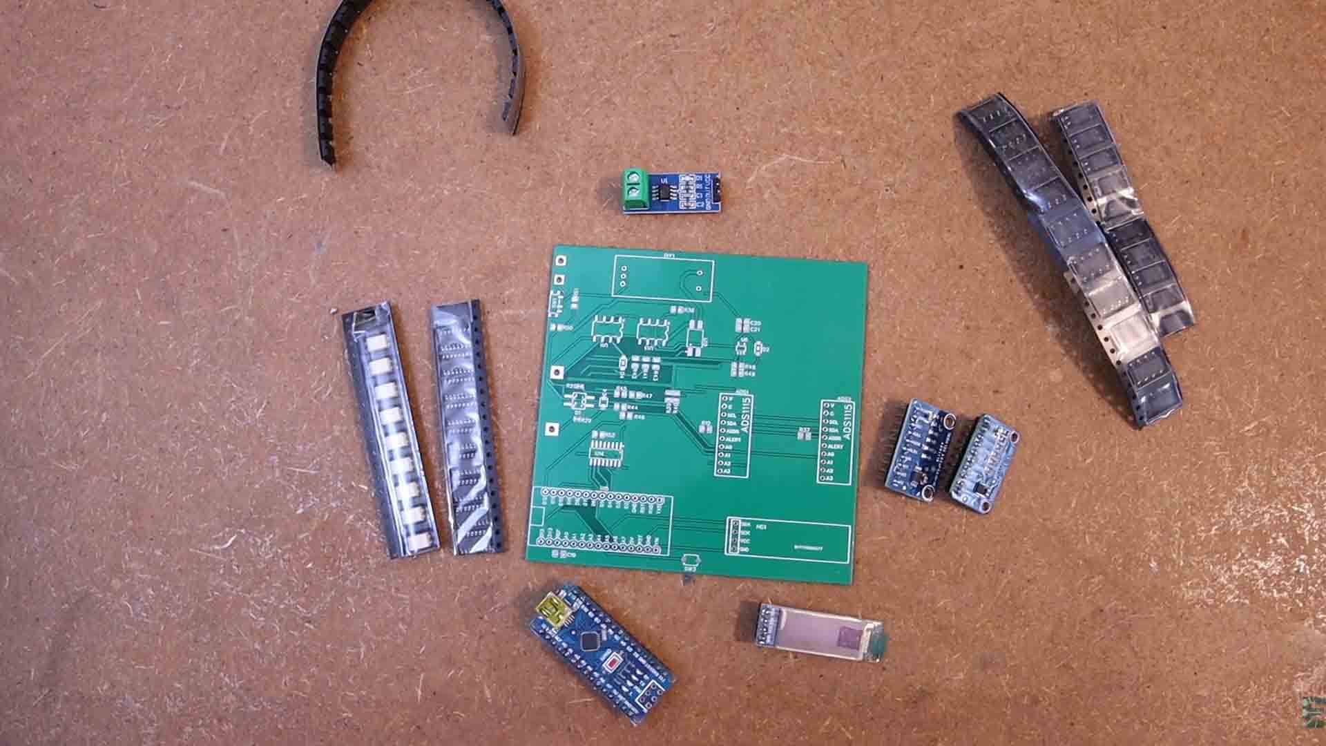
So, different from my previous multimeter circuit, this PCB has two external ADCs and you will see why. It still has the ACS712 current meter so we will also need a module like this one. To display values, we have an OLED screen with i2c communication.
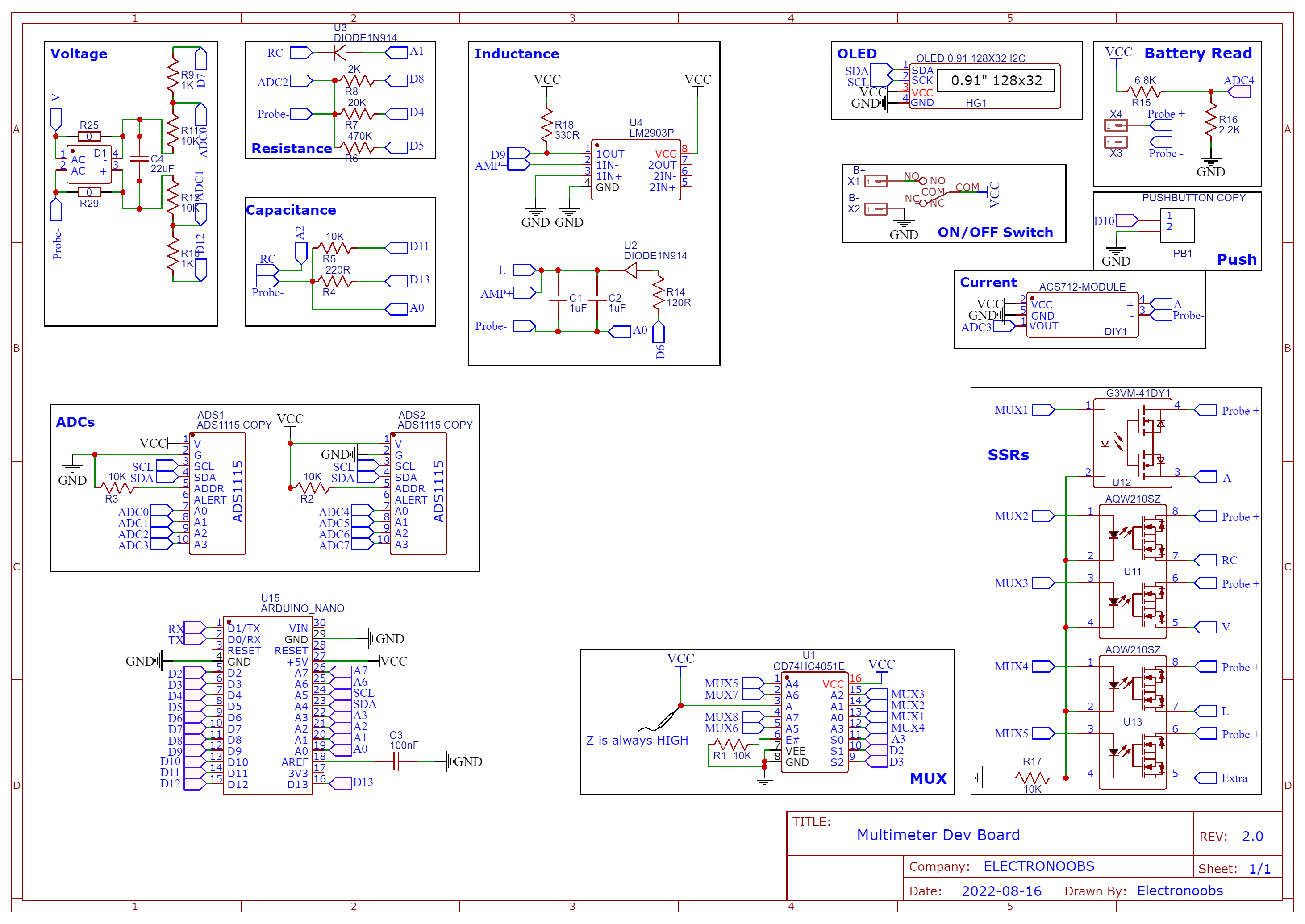
Compared with the previous schematic, the different parts are the two blocks on the schematic with the SSRs and MUX. You see, for previous multimeters, to change modes, we were using a rotary switch which is very big or some sliding switches that have to move at the same time, and that’s not working that good. If you want to implement automatic mode switch, we need solid state relays, in this case the G3VM41D for current mode and the AQW210 for the rest of the modes.
Since the Arduino doesn't have enough pins, to control each of these relays, we use this multiplexor, the 74HC4051. For the rest of the modes, we only need resistors, capacitors, a small operational amplifier and a full bridge rectifier. Ok, so let’s assemble everything and try some different modes.
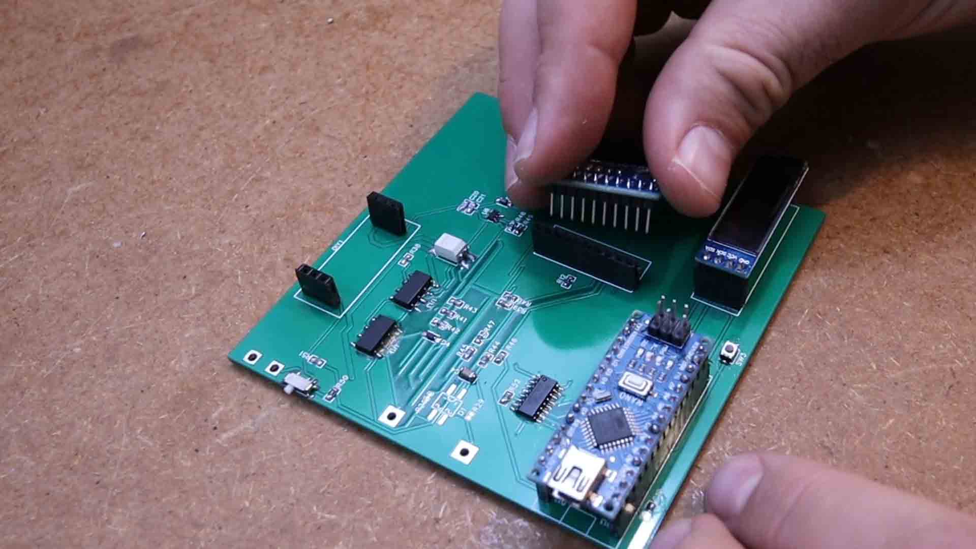
Assembling the PCB is very easy. I've made it to use through hole components so it would be easier to solder. Only the SSRs are SMD but they are easy to solder as well. The rest are using modules and male-female pins so is easy to connect them. So get the PCB from PCBWAY.com. and solder all the DIP components and the female pins for the mdoules. Then just add the mdoules and we are ready to go. We can supply the PCB from the USB connectro with 5V for these tests. Check the next chapters for each example.
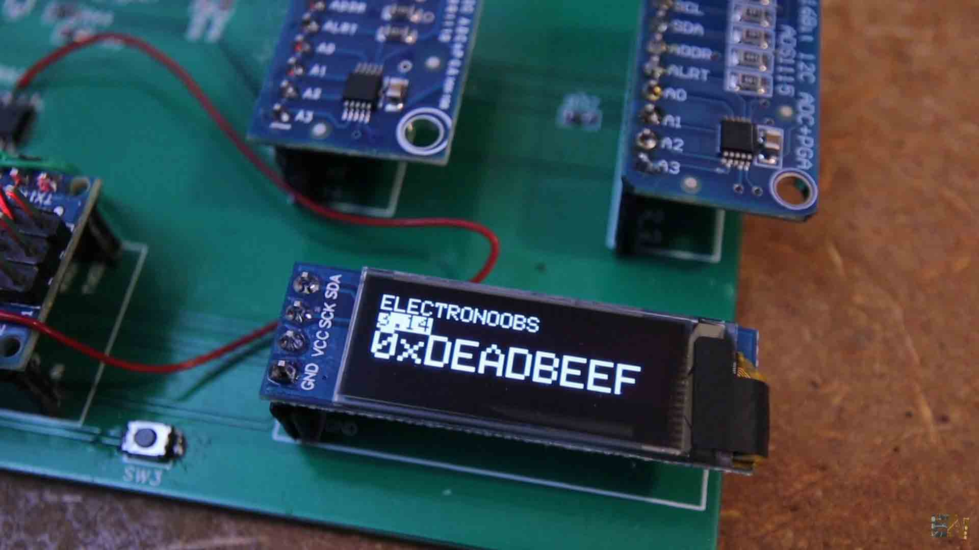
First example is the OLED control. Download the example code from below and upload it to the Arduino. Make sure you also download and install the library for the OLED screen. This code will teach you how to use the OLED screen and print text of different sizes and in different positions. So select the Arduino NANO board on the Arduino IDE, connect the Arduino to the USB cable and upload the code. As you can see, we can use the OLED screen. So check the code on electronoobs.com and learn how to use it.
The next example is to read voltage. As you can see on the schematic above, the voltage block has two resistors of 0 ohms. Basically, if you short circuit those pads on the PCB, we jump over the rectifier and that’s because we first only measure DC voltage. This rectifier might introduce some voltage drop and we don’t want that for now. So I short circuit those pads with solder. As you can see, the connections for the voltage mode are controlled with the multiplexor so we need to activate the MUX 3 pin. In the code I set all MUX pins to low and the MUX3 to high using the multiplexor. This multiplexor is controlled with 3 pins from the Arduino, pins A3, D2 and D3.
So download the voltage read code from below. In this code, remember to add the OLED library from before but also the library for the ADS1115 external ADC, since we will use that to measure voltage with precision. Since we have two ADC modules, to have different i2c addresses, on the schematic, one module has the ADDR pin connected to ground and the other one the ADDR pin connected to VCC so one will have different i2c address. In this code we use the ADC functions and read the voltage between ADC0 and ADC1. Since the input has a voltage divider of 11, we multiply the voltage value by 11 and we get the real voltage. We have to set all the unused pins as inputs in order to have high impedance and not affect the rest of the circuit.
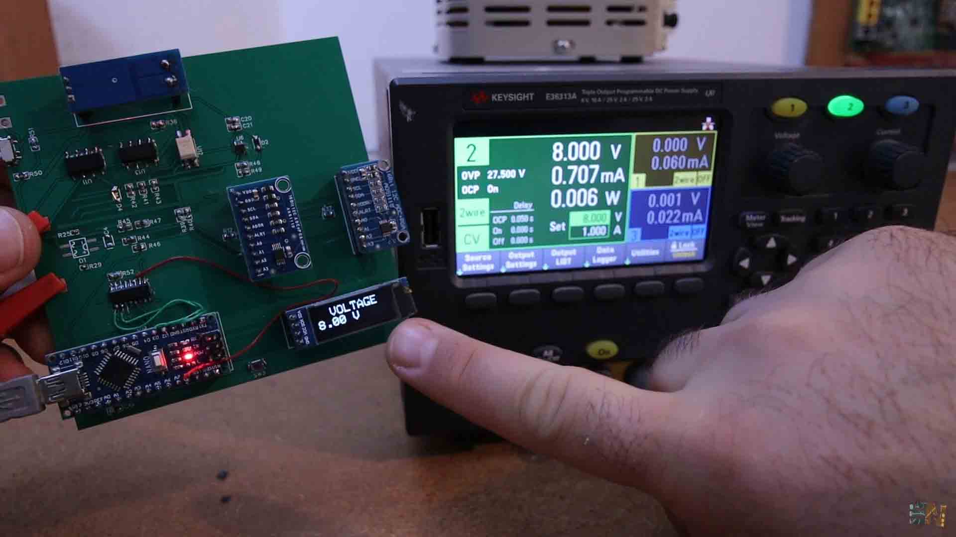
Upload this code and we test it out. I connect the power supply at the input and apply 5V for example. Then, I try different values and as you can see in the video, the voltage value is the same as on the supply, so the voltage mode works. The ADS1115 is capable of measuring negative voltage as well so if we invert the probes, we can still measure the voltage and it will appear negative on the screen. Since the divider is of 11 and the ADC could take up to 5V, the maximum voltage we can measure is around 50V DC.
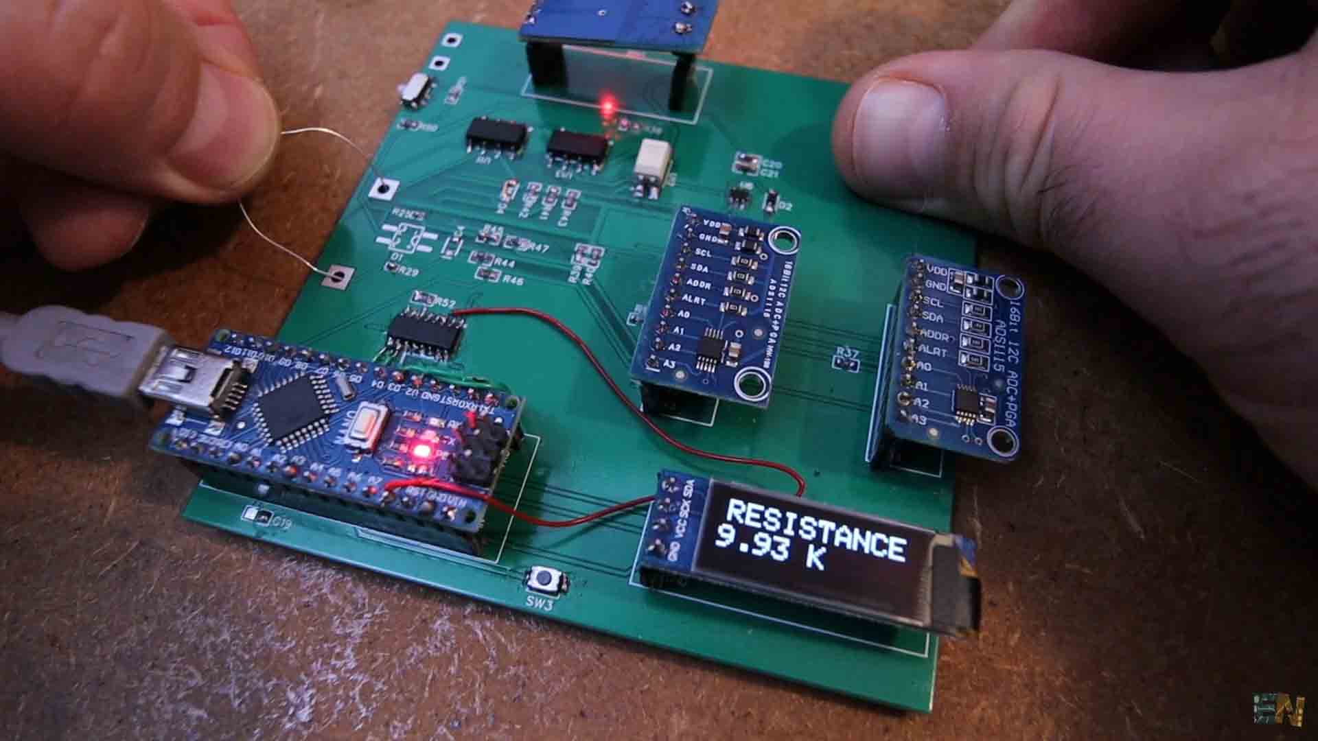
The next example is for measuring resistance. For that we use the block with 3 resistors and a diode. So we need to activate the relay for the RC pin by setting MUX2 to high. Then, in the code we decide the range and according to that, we set to low one of these pins, D8, D4 or D5 in order to change the scale. At the same time we also read the battery voltage of the multimeter with a separate block on the scheamtic. That’s why we need two external ADCs, because only 4 inputs was not enough. We need to know the VCC voltage in order to calculate resistance. So in the code we use the ADC and measure the VCC voltage. Then the voltage over the resistance divider. Using ohm law, we get the resistance value. We print the value on the OLED display.
The inductance mode was the one that faced problems for the previous PCB. You see, the inductance mode uses two capacitors of 1uF to create a resonating oscillation. One side of the capacitor is connected to the negative probe and the other side to the coil that we want to measure. The problem with the previous board without the relays, is that the same pin of the inductance mode was shared with the rest of the resistance and capacitance measurement. As you can see on the previous schematic, that pin was called RLC. But now, using the relays, we can separate the RC from the L. Otherwise, the capacitors would be connected to the other measuring blocks and would change their values and we couldn’t read correctly.
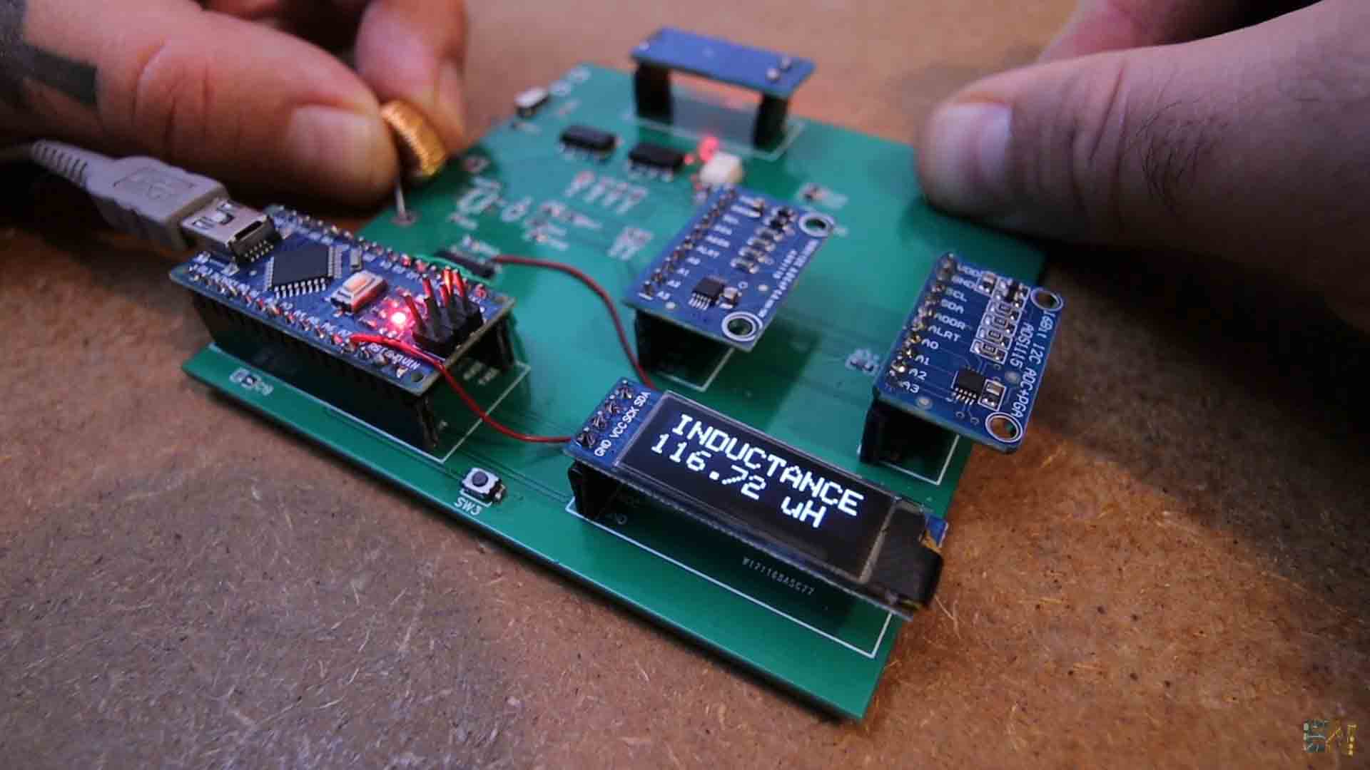
Anyway, for the code, we apply a pulse to the LC tank and create oscillations. We read the frequency of those oscillations with the pulse in function and using a simple formula and knowing that the capacitance is of 2uF, we can get the inductance value. We print that on the OLED display and test it out. I connect a 100uH inductor and once again, it works great and we can also measure inductance with this development board.
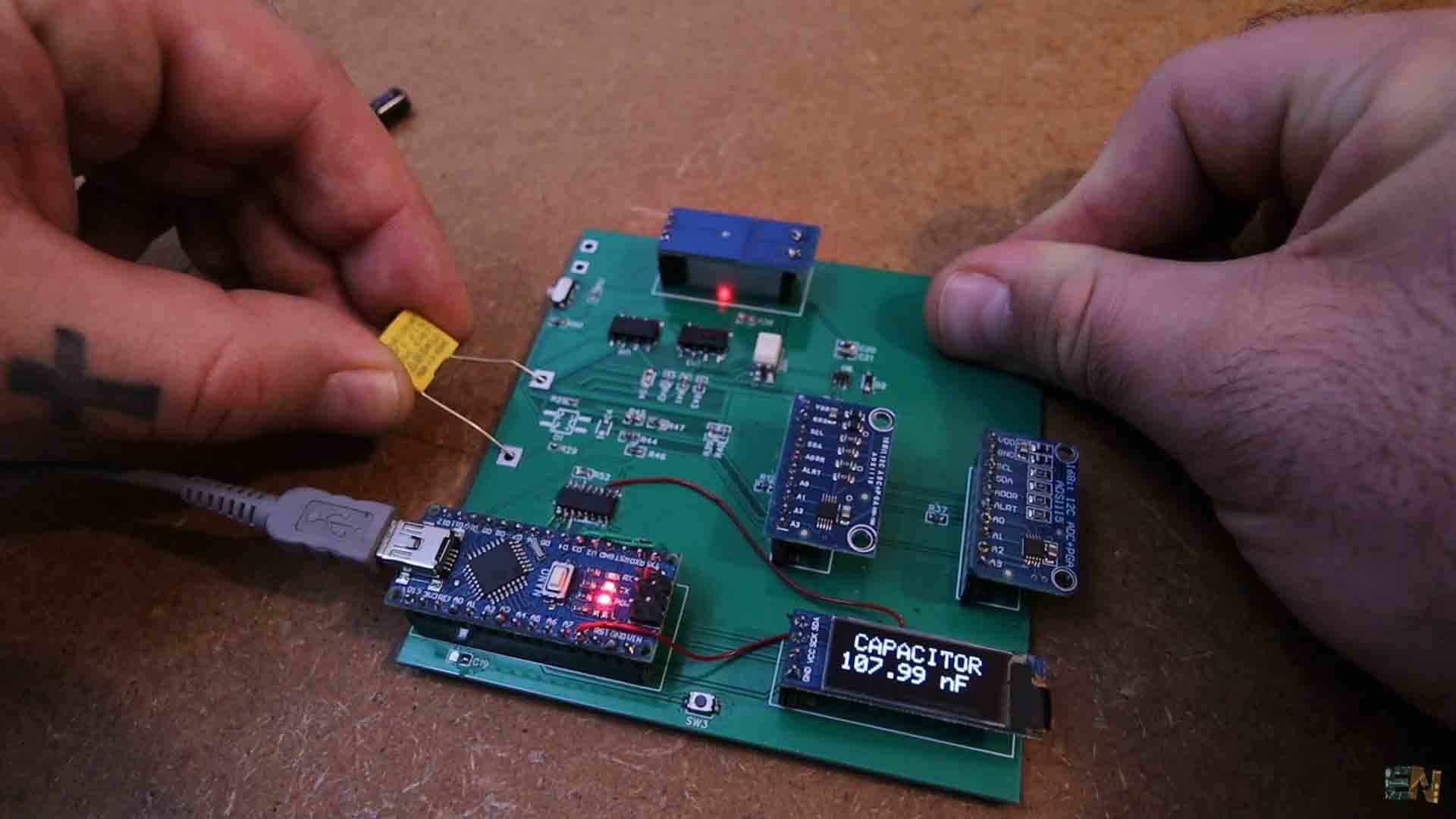
To measure capacitance is very easy. We use two resistors to charge and discharge the capacitor. In the code, we count the time it takes the capacitor to get to 63%. Then we calculate the capacitance value. You have more details about this 63% value on the tutorial on here. Run the code and test it out. Here is a 100nF capacitor. How here is one of just 1nF and finally a 47uF capacitor which takes a bit longer to charge and discharge. But it works.
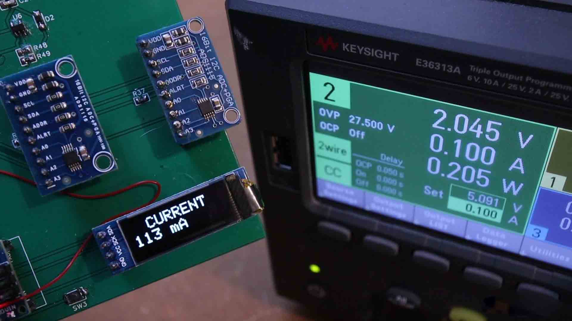
Finally, the current measurement is very easy. We disable the two relays and we activate the other one. That model could handle more current for the current mode. Then, in the code, we measure the voltage from the ACS712 current meter. We apply the formula for the 5A model and we get the current value. Print that on the screen and test it out. I connect it to my power supply and start applying different current values. We have a small positive offset but now, all the main parts are working.
We could also measure frequency, diode mode, continuity, but that would be extra. Now I could make the final version of my two-hand multimeter and I think that would be an amazing project. A multimeter based on Arduino capable of measuring so many values. So guys, get the PCB files and order it at PCBWAY.com and start learning all these parts with help from my tutorials on this website. I hope this will help you understand more how Arduino works.
If my videos help you, consider supporting my work on my PATREON or a donation on my PayPal. Thanks again and see you later guys.