WiFi YouTube subscribers counter
This is a very nice project and so easy to build. All we need is a WiFi module and a screen to print the values. Using the ESP8266 WiFi module we connect to the internet. Once connected, using the YouTube channel ID and the API key we obtain the YouTube subscribers count and then we print that value to a 7 segments screen module. The code refresh itself and it will beep each time the value changes.
To make it look nice, I've 3D printed the case, fit everything inside and power the system using a USB connector. We could also obtain the views, videos and time ratings and print those values as well.
0.0 Material
This project is simple. The total price is under 10 dollars. If you don't have a 3D printer you should create any kind of small case and fit everything in place. So lets see what we need.
Find the full part list and best prices here:
7 segment module: LINK eBay
Wemos D1 R2 mini: LINK eBay
Buzzer: LINK eBay
3D printed case (DIY)
1.0 Schematic
The schematic is very simple. Just connect the data, load and clock pins from the 7 segment module to pins D4, D3 and D2 of the WeMos D1 R2 mini board. Also connect the buzzer to the board. To supply the circuit we will use directly the USB connector with a voltage of 5 volts.

2.0 Case
The case is 3D printed. You could find the STL files in a link below. Print the file using 2 perimeters, 20% infill. I've used a 0.4mm nozzle and the Anet E10 3D printer. Fit everything iside the case and pass the USB cable through the hole. Close the case and that's it. You could add some nice front labels to make it look cooler.
Downlaod the STL files for the case here:3.0 Code
3.1 Install ESP8266 core

Before we look at the code we have to prepare the Arduino IDE with the libraries and also the core for the WeMos development board. To install the WeMos with the ESP8266 module core you have to:
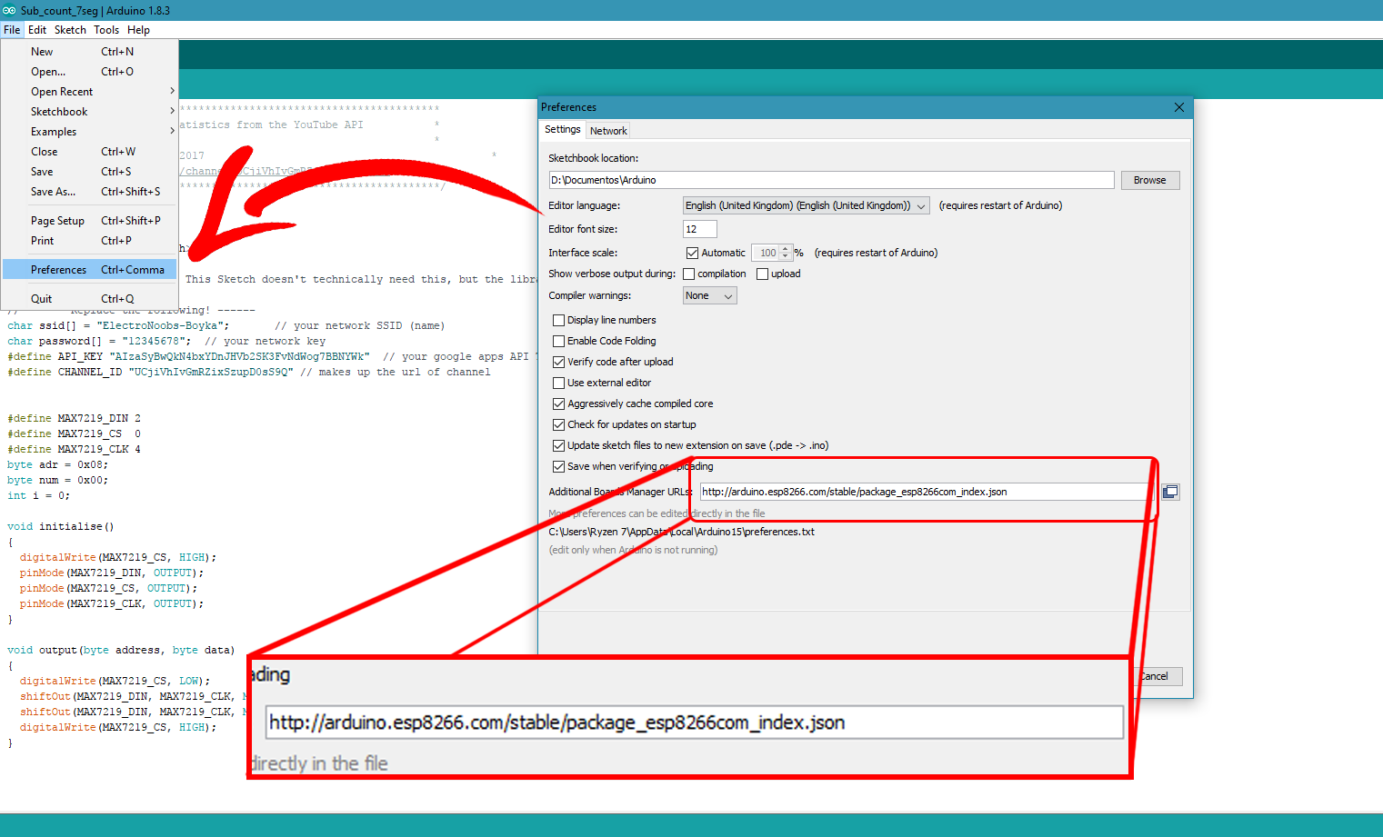
-Add the next line in to the

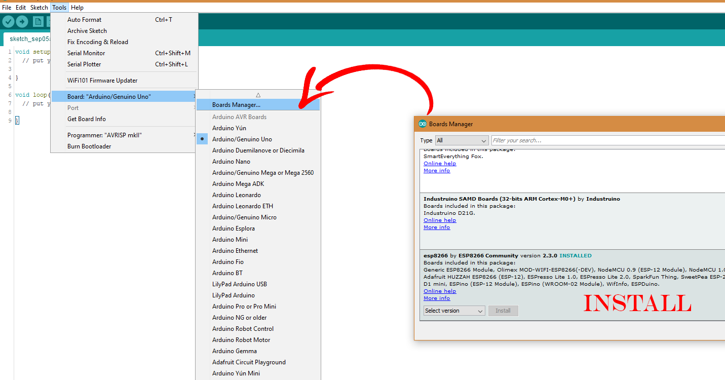
Open Arduino IDE, go to preferences and add the line there. If you already have URL added just type a comma (,) and add the new URL. Ok, now that we've done that we can go in to boards manager and search for the needed board. For that go to tools, board, boards manager. Now that we have the URL added into the Arduino preferences the ESP8266 installing file will also appear here. Select it and press install. Once installed you should probably restart Arduino IDE.

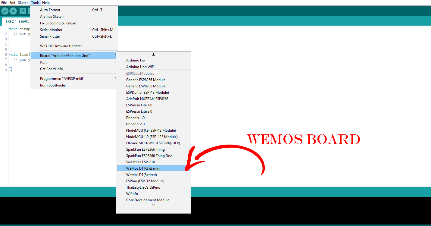
Now if we go to boards you can see that I have a lot of extra boards added. We will use the WeMos D1 R2 board. If this doesn’t work then you should use the downloaded ZIP below. Extract the zip and copy the content into the Arduino directory, into hardware, ESP8266COM and a new folder called ESP8266. Now you should restart the IDE and try if it works.
Download the ESP8266 board core here:
3.2 The 7 segments display
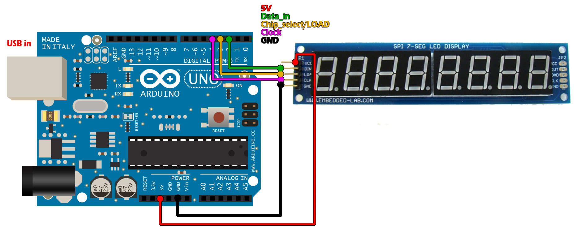
The thing is that we could send serial data to this module using just 3 pins. Those pins are clock, chip select and data. I’ll show you an example of that right now. I’ll connect the module to the Arduino UNO for the test. Data is pin 2, chip select is 3 and clock will be 4. All we need now to do is to shift some registers containing our data. For that I open this example that you could also download form a link below.
Download the 7 segment example (Arduino UNO)
Open the code above in the Arduino IDE and upload it to the Arduino uno and mount the next schematic.
The shift function will first activate the chip select pin which is activated by a low value. Next it will create the data on the data input pin by shifting the value that we want. In this case it will first be the address of the corresponding register on the 7 segments module. This action is followed by the same thing but with the sent data. Finally set the chip select to high and the transmission is done.
Ok, so in the setup void, we define those pins as output and send the configuration data. As you can see in the code I send the address of the register and the value using the shift function. If we check the datasheet of this chip on page 7 we can see the address for the intensity, mode and shutdown. We send the corresponding value to make the display show the numbers from right to left. Next, in the infinite loop, we just send the data for each 7 segment display. Easy right.

Ok, so now we know how to print numbers on this module. Let’s see how to obtain the YouTube subscribers value.

 About me
  History
  Let's learn
  Contact us
  Arduino tutorials
 Circuits tutorials
  Robotics tutorials
 Q&A
Q&A Blog
Blog  Arduino
  Circuits
 Robotics
  Modules
  Gadgets
  Printers
  Materials
  3D objects
  3D edit
  Donate
  Reviews
  Advertising


