About me
  History
  Let's learn
  Contact us
  Arduino tutorials
 Circuits tutorials
  Robotics tutorials
 Q&A
Q&A Blog
Blog  Arduino
  Circuits
 Robotics
  Modules
  Gadgets
  Printers
  Materials
  3D objects
  3D edit
  Donate
  Reviews
  Advertising


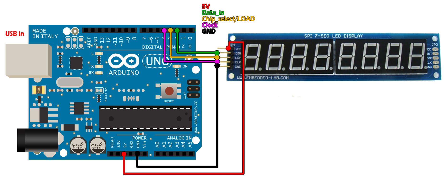
7 segment module and Arduino
Download the .zip file below. Unzip it and open it in Arduino IDE. Compile and upload.
/*
 * http://www.electronoobs.com
 * http://www.youtube.com/c/ELECTRONOOBS
 *
 * Like, Share and Subscribe, Thank you!!!!
 */

//Outputs
#define MAX7219_Data_IN 2
#define MAX7219_Chip_Select  3
#define MAX7219_Clock 4


//The shift function
void shift(byte send_to_address, byte send_this_data)
{
  digitalWrite(MAX7219_Chip_Select, LOW);
  shiftOut(MAX7219_Data_IN, MAX7219_Clock, MSBFIRST, send_to_address);
  shiftOut(MAX7219_Data_IN, MAX7219_Clock, MSBFIRST, send_this_data);
  digitalWrite(MAX7219_Chip_Select, HIGH);
}

void setup() {
  //Define the pins as outputs and disable CS
  pinMode(MAX7219_Data_IN, OUTPUT);
  pinMode(MAX7219_Chip_Select, OUTPUT);
  pinMode(MAX7219_Clock, OUTPUT);
  digitalWrite(MAX7219_Chip_Select, HIGH);
  delay(200);
  //Setup
  shift(0x0f, 0x00); //display test register - test mode off
  shift(0x0c, 0x01); //shutdown register - normal operation
  shift(0x0b, 0x07); //scan limit register - display digits 0 - 7
  shift(0x0a, 0x0f); //intensity register - max brightness
  shift(0x09, 0xff); //decode mode register - CodeB decode all digits
}

void loop() {
  //Data transfer
  shift(0x01, 0x0f);
  shift(0x02, 0x00);//O
  shift(0x03, 0x0D);//L
  shift(0x04, 0x0D);//L
  shift(0x05, 0x0B);//E
  shift(0x06, 0x0C);//H
  shift(0x07, 0x0f);
  shift(0x08, 0x0f);
  delay(1000);
  }