
First of all, this is jst a first prototype. It works but I can't know all the results for sure and if it is reliable or not. Stay tuned for future versions with improvements, more tests and better code. In this tutorial I will explain you the parts of an MPPT controller, the charging process of a 12V led-acid battery, the code and components for the project and show you some results. The controller could keep a constant voltage, constant current, activate or deactivate load with a relay, have a maximum current limit and print on the screen the voltage, current and power values. I really think this is an interesting project that we could improve in future versions. So guys, let’s get started.
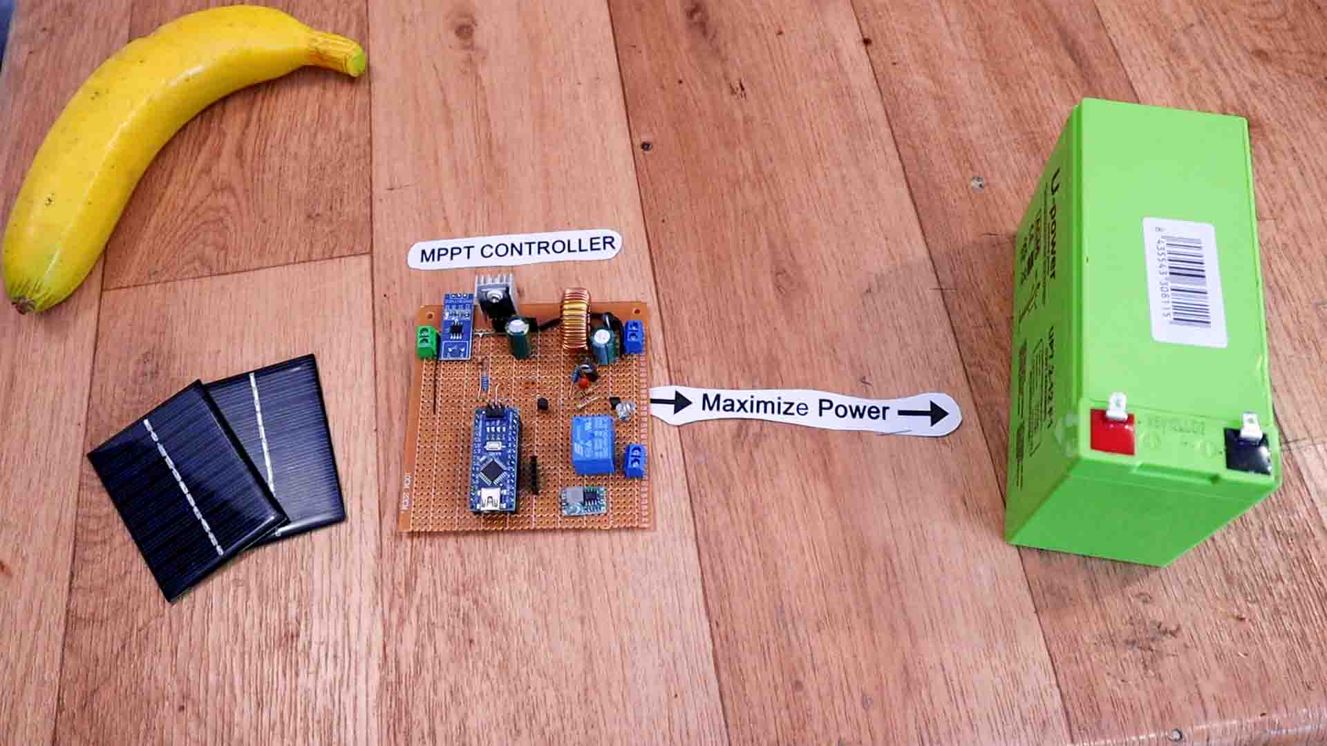
First, let’s see what is an MPPT controller. The MPPT technique is commonly used with wind turbines and or solar panel systems to maximize power extraction under all conditions. Solar panels for example, give DC output. But this output is not stable, it depends on the amount of sunlight, the panel power, the temperature and so on. So, if you want to power a load, let’s say a DC motor, is not recommended to connect the load directly to the solar panel. What we do is to first charge a battery and then get the power from the battery and not directly from the solar panel. But to charge the battery and control the power from the panel, we need this MPPT controller and that’s what we will build today.
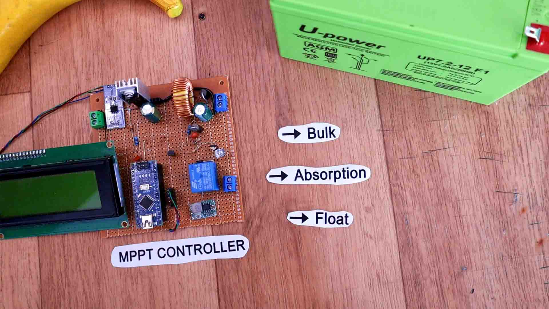
The MPPT controller is in charge of: 1. charging the battery in different modes. 2. Protect both the battery and the solar panel of overcurrent, 3. enable or disable the load when the battery is undervoltage and also 4. keep track of the charged capacity. This type of batteries require 3 stages of charging. When the battery is discharged, we first stary in the A. bulk mode at a constant current set by the battery manufacturer. In this mode the battery would charge up to about 80%. When we reach a certain voltage, we then pass to the B. absorption stage. In this mode we don’t have constant current anymore but constant voltage. The voltage is kept by the controller at a specific value and we would see the current getting lower and lower while the battery is charging the last 20%. When the current value gets below a certain value, we enter the last stage which is called C. float. In float mode, the controller reduces the voltage to another preset value and keeps a current flow less than 1% of the battery capacity. This will keep a battery fully charged indefinitely.
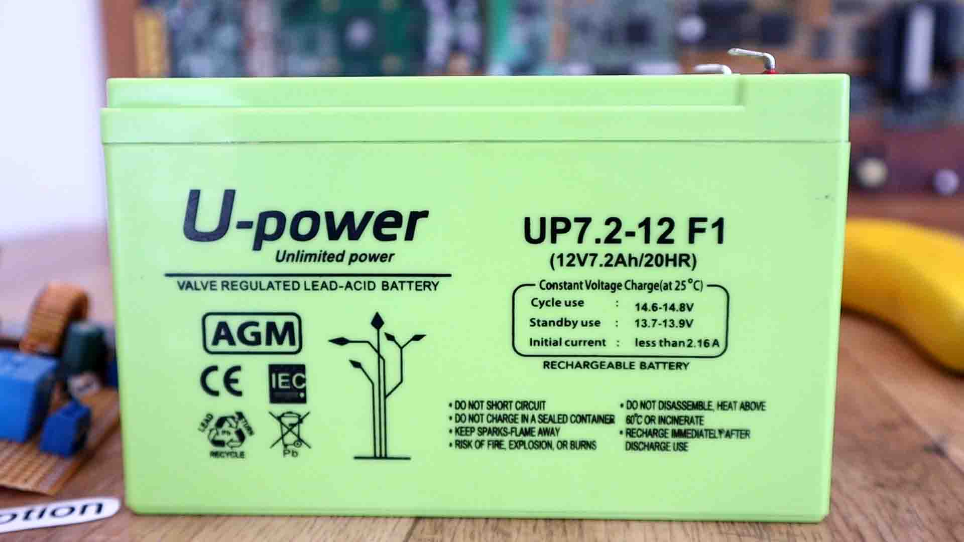
In my case, for this tutorial I have a 12V battery. For this battery the bulk maximum voltage is 14.6V and a charging current of 2A. When 14.6V are reached, we enter absorption mode and we keep this value till the current drops below let’s say 100mA. Then we enter float mode and we keep the battery art 13.7V indefinitely at a very low current flow. I don’t have a huge solar panel because I leave in an apartment. To simulate a solar panel, I will use my power supply. Usually, you can buy panels of 12V, 24V or 36V. Remember this voltage will eb affected by the sunlight, temperature and more. So, now that we know what we have to do, let’s build the controller.
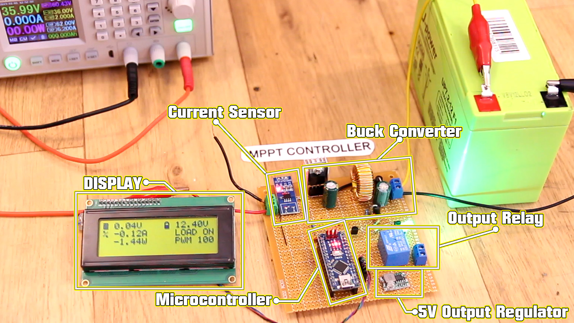
First, what are the parts of an MPPT controller. We need a microcontroller able to read input and output voltage, current values and process the calculations. Of course, the Arduino will do that. We need a variable buck converter that will be able to regulate the output voltage and keep it constant. We will make this circuit ourselves and control it with a PWM signal from the Arduino. We need current sensors in order to read and limit the current value. For that I will use the ACS712 module. We need a relay or a MOSFET that will be used to enable or disable the load. We need a display where we can print the values. I will use this 20 by 4 LCD. We should also have a fixed value buck converter set to 5V that will supply the Arduino. For that we could a small 2amps buck converter. Set it to 5V and then glue the potentiometer so it will stay at that voltage.
Below you have the prototype schematic. Remember that in the video I've used a BC547 NPN at the gate of the MOSFET but is better to use a PNP and have always a pulldown at the gate of the MOSFET for safety. The current sensor is the model of 5A but you could use any oter but remember to change the multiplier in the code. As for the relay, you could buy directly a module and don't use the small NPN to activate it. For the power lines I recommend you to buy thick copper wire. Get the small buck converter and fix it to 5V and glue the potentiometer. Please check the part list above and the vvalues on the schematic below.
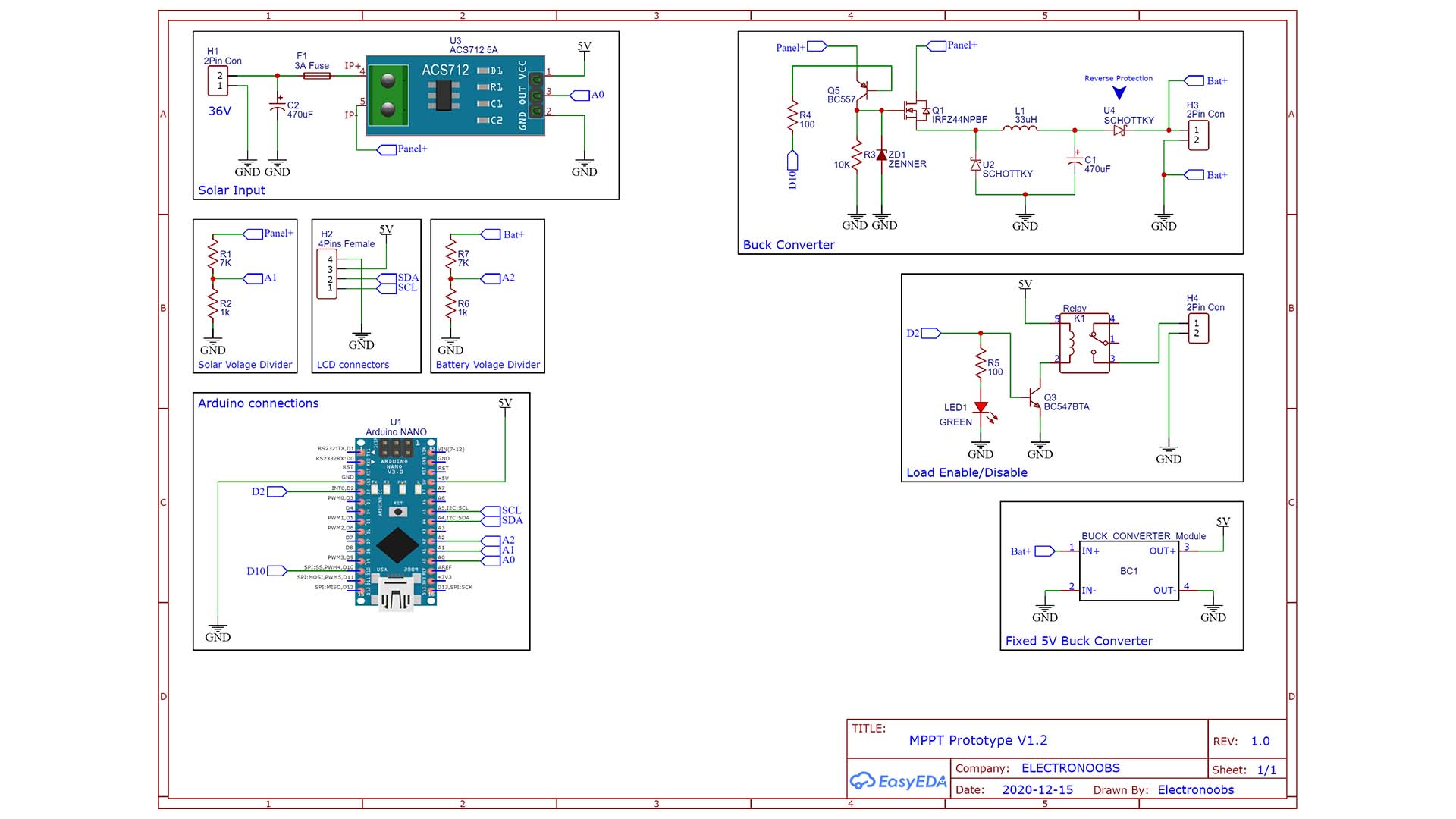
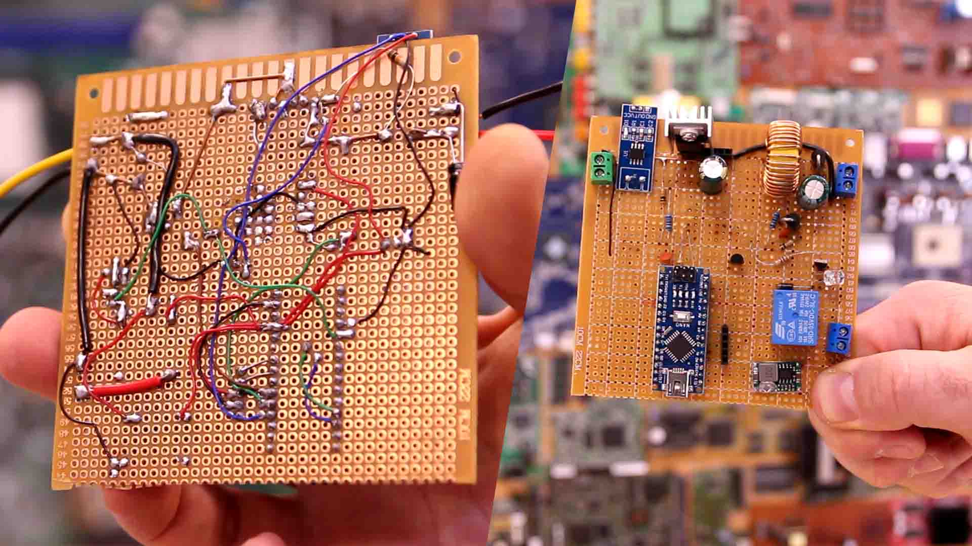
In my case I’ve used a piece of prototyping PCB and soldered everything on it. I’ve used female pins so in case I damage something, I could change it easily. Remember this is still a prototype and I will perform a lot of tests. So if for example the MSOFET gets burned out I won’t have to de-solder and solder a new one. I also make sure to add a small heat dissipator on the MSOFET which by the way, if this wasn’t a prototype it should be a lot bigger. To read the voltage I use a voltage divider. Voltage could be high up to 36V from the solar panel so we can’t read that with the Arduino. So with a 1k and a 7K resistor I make some voltage divide and lower the value under 5V for the Arduino ADC.
Ok, let’s make some tests. I upload a small code (see below) that will limit the current at 1 amp. I connect 36V at the input and a load at the output. In this mode we don’t care about the voltage, only the current value. How this works? Well, if the Arduino detects with the sensor that the current is higher than 1 amp, it will lower the PWM signal applied to the MOSFET. If the current value is lower than 1 amp, it will increase the duty cycle. We do this fast enough so the current stays at that value.
//Libraries
#include <Wire.h>
#include <LiquidCrystal_I2C.h>
LiquidCrystal_I2C lcd(0x27,20,4);  //LCD i2c adress sometimes 0x3f or 0x27


//Constants
#define LCD_refresh_rate 1000

//Inputs
#define solar_current_in A0

//Outputs
#define PWM_out 10
#define load_enable 2

//Variables
int pwm_value = 0;
float solar_current = 0;
float current_factor = 0.185;       //Value defined by manufacturer ACS712 5A

unsigned int before_millis = 0;
unsigned int now_millis = 0;


void setup(){
  pinMode(solar_current_in,INPUT);    //Set pins as INPUTS

  pinMode(PWM_out,OUTPUT);            //Set pins as OUTPUTS
  digitalWrite(PWM_out,LOW);          //Set PWM to LOW so MSOFET is off

  TCCR1B = TCCR1B & B11111000 | B00000001; //timer 1 PWM frequency of 31372.55 Hz
  Serial.begin(9600);

  lcd.init();                 //Init the LCD
  lcd.backlight();            //Activate backlight

  before_millis = millis;     //Used for LCD refresh rate
}

void loop(){
  solar_current = get_solar_current(10);

  now_millis = millis();
  if(now_millis - before_millis > LCD_refresh_rate)
  {
    before_millis = now_millis;
    //lcd.clear();
    lcd.setCursor(0,0);               //Column 0 row 0
    lcd.print(solar_current,2);       //Soalr voltage
    lcd.print("A");                   //Volts
  }

  ///////////////////////////////////////////////
  //CONSTANT CURRENT CONTROL//
  if(solar_current > 1.0){                                    //Constant 1A current
    pwm_value--;
    pwm_value = constrain(pwm_value,0,254);
  }

  else {
    pwm_value++;
    pwm_value = constrain(pwm_value,0,254);
  }
  analogWrite(PWM_out,pwm_value);
  ///////////////////////////////////////////////
  ///////////////////////////////////////////////

}//End void loop


/////////////////////////FUNCTIONS/////////////////////////
///////////////////////////////////////////////////////////
float get_solar_current(int n_samples)
{
  float Sensor_voltage;
  float current =0;
  for(int i=0; i < n_samples; i++)
  {
    Sensor_voltage = analogRead(solar_current_in) * (5.0 / 1023.0);
    current = current + (Sensor_voltage-2.5)/current_factor;
  }
  current = current/n_samples;
  return(current);
}
Now I upload another code that will keep the voltage at a constant value. I set it to 12 volts. O connect 36V at the input but the voltage is always 12V at the output as you can see. Even if I add a load that will draw a lot of current, the voltage is still 12V. I change this line in the code and now set the voltage to 10V. Now the output is constant at 10V. So, that easy we can control the voltage and current just by changing the PWM duty cycle that is connected to the buck converter MOSFET. Controlling the current and voltage, we can make out code for the MPPT. Remember from the beginning we have 3 stages, bulk, absorption and float stage for the battery charging process.
//Libraries
#include <Wire.h>
#include <LiquidCrystal_I2C.h>
LiquidCrystal_I2C lcd(0x27,20,4);  //LCD i2c adress sometimes 0x3f or 0x27

//Inputs
#define battery_voltage_in A2

//Outputs
#define PWM_out 10
#define load_enable 2

//Variables
float bat_voltage = 0;
int pwm_value = 0;
unsigned int before_millis = 0;
unsigned int now_millis = 0;
#define LCD_refresh_rate 1000


void setup(){
  pinMode(battery_voltage_in,INPUT);        //Set pins as INPUTS

  pinMode(PWM_out,OUTPUT);                  //Set pins as OUTPUTS
  digitalWrite(PWM_out,LOW);                //Set PWM to LOW so MSOFET is off
  TCCR1B = TCCR1B & B11111000 | B00000001;  //timer 1 PWM frequency of 31372.55 Hz
  Serial.begin(9600);

  lcd.init();                     //Init the LCD
  lcd.backlight();                //Activate backlight

  before_millis = millis;         //Used for LCD refresh rate
}

void loop(){
  bat_voltage =   get_battery_voltage(10);

  now_millis = millis();
  if(now_millis - before_millis > LCD_refresh_rate)
  {
    before_millis = now_millis;
    //lcd.clear();
    lcd.setCursor(0,0);               //Column 0 row 0
    lcd.print(bat_voltage,2);       //Soalr voltage
    lcd.print("V");                   //Volts
  }

  ///////////////////////////////////////////////
  //CONSTANT VOTLAGE CONTROL//
  if(bat_voltage > 12.0){
    pwm_value++;
    pwm_value = constrain(pwm_value,0,254);
  }
  else {
    pwm_value--;
    pwm_value = constrain(pwm_value,0,254);
  }
  analogWrite(PWM_out,pwm_value);
  ///////////////////////////////////////////////
  ///////////////////////////////////////////////

}//End void loop


/////////////////////////FUNCTIONS/////////////////////////
///////////////////////////////////////////////////////////
float get_battery_voltage(int n_samples)
{
  float voltage = 0;
  for(int i=0; i < n_samples; i++)
  {
    voltage += (analogRead(battery_voltage_in) * (5.0 / 1023.0) * 7.85);
  }
  voltage = voltage/n_samples;
  return(voltage);
}
This is the code for the MPPT control. Make the connections as in the schematic before and use i2c connection for the display. You will also need to download and install the i2c liquid crystal library from the link below. In bulk we limit the current and we don’t care about the voltage while the battery is charging up. Then, in absorption we keep a constant voltage and the current value wild drop and drop. Finally, in float mode we keep a constant lower voltage and a very low current value. Download or copy+paste the code from below.
//Libraries
#include <Wire.h>
#include <LiquidCrystal_I2C.h>
LiquidCrystal_I2C lcd(0x27,20,4);  //LCD i2c adress sometimes 0x3f or 0x27

//Icons
uint8_t Battery[8]  = {0x0E, 0x1B, 0x11, 0x11, 0x1F, 0x1F, 0x1F, 0x1F};
uint8_t Panel[8]  = {0x1F, 0x15, 0x1F, 0x15, 0x1F, 0x15, 0x1F, 0x00};
uint8_t Pwm[8]  = {0x1D, 0x15, 0x15, 0x15, 0x15,0x15, 0x15, 0x17};
uint8_t Flash[8]  = {0x01, 0x02, 0x04, 0x1F, 0x1F, 0x02, 0x04, 0x08};


//Constants
#define bulk_voltage_max 14.5
#define bulk_voltage_min 13
#define absorption_voltage 14.7
#define float_voltage_max 13
#define battery_min_voltage 10
#define solar_min_voltage 19
#define charging_current 2.0
#define absorption_max_current 2.0
#define absorption_min_current 0.1
#define float_voltage_min 13.2
#define float_voltage 13.4
#define float_max_current 0.12
#define LCD_refresh_rate 1000
byte BULK = 0;        //Give values to each mode
byte ABSORPTION = 1;
byte FLOAT = 2;
byte mode = 0;        //We start with mode 0 BULK

//Inputs
#define solar_voltage_in A1
#define solar_current_in A0
#define battery_voltage_in A2

//Outputs
#define PWM_out 10
#define load_enable 2

//Variables
float bat_voltage = 0;
int pwm_value = 0;
float solar_current = 0;
float current_factor = 0.185;       //Value defined by manufacturer ACS712 5A
float solar_voltage = 0;
float solar_power = 0;
String load_status = "OFF";
int pwm_percentage = 0;
unsigned int before_millis = 0;
unsigned int now_millis = 0;
String mode_str = "BULK";


void setup(){
  pinMode(solar_voltage_in,INPUT);    //Set pins as inputs
  pinMode(solar_current_in,INPUT);
  pinMode(battery_voltage_in,INPUT);

  pinMode(PWM_out,OUTPUT);            //Set pins as OUTPUTS
  digitalWrite(PWM_out,LOW);          //Set PWM to LOW so MSOFET is off
  pinMode(load_enable,OUTPUT);
  digitalWrite(load_enable,LOW);      //Start with the relay turned off
  TCCR1B = TCCR1B & B11111000 | B00000001; //timer 1 PWM frequency of 31372.55 Hz
  Serial.begin(9600);

  lcd.init();                 //Init the LCD
  lcd.backlight();            //Activate backlight

  lcd.createChar(0, Battery);
  lcd.createChar(1, Panel);
  lcd.createChar(2, Pwm);
  lcd.createChar(3, Flash);
  before_millis = millis;     //Used for LCD refresh rate
}

void loop(){
  solar_voltage = get_solar_voltage(15);
  bat_voltage =   get_battery_voltage(15);
  solar_current = get_solar_current(15);
  solar_power = bat_voltage * solar_current;
  pwm_percentage = map(pwm_value,0,255,0,100);

  now_millis = millis();
  if(now_millis - before_millis > LCD_refresh_rate)
  {
    before_millis = now_millis;
    lcd.clear();
    lcd.setCursor(0,0);               //Column 0 row 0
    lcd.write(1);                     //Panel icon
    lcd.print(" ");                   //Empty space
    lcd.print(solar_voltage,2);       //Soalr voltage
    lcd.print("V");                   //Volts
    lcd.print("    ");                //Empty spaces
    lcd.write(0);                     //Battery icon
    lcd.print(" ");                   //Empty space
    lcd.print(bat_voltage,2);         //Battery voltsge
    lcd.print("V");                   //Volts

    lcd.setCursor(0,1);               //Column 0 row 1
    lcd.print("  ");                  //Empty spaces
    lcd.print(solar_current,2);       //Solar current
    lcd.print("A");                   //Ampers
    lcd.print("     LOAD ");           //Print LOAD
    lcd.print(load_status);           //LOAD status

    lcd.setCursor(0,2);               //Column 0 row 2
    lcd.print("  ");                  //Empty spaces
    lcd.print(solar_power,2);         //Solar power
    lcd.print("W");                   //Watts
    lcd.print("     PWM ");           //Print PWM
    lcd.print(pwm_percentage);        //PWM value
    lcd.print("%");                   //Percentage

    lcd.setCursor(0,3);               //Column 0 row 3
    lcd.print(mode_str);              //Print the mode

  }

  if(bat_voltage < battery_min_voltage){
    digitalWrite(load_enable,LOW);        //We DISABLE the load if battery is undervoltage
    load_status  = "OFF";
  }
  else{
    digitalWrite(load_enable,HIGH);       //We ENABLE the load if battery charged
    load_status  = "ON";
  }

  ///////////////////////////FLOAT///////////////////////////
  ///////////////////////////////////////////////////////////
  if(mode == FLOAT){
    if(bat_voltage < float_voltage_min){
      mode = BULK;
      mode_str = "BULK";
    }

    else{
      if(solar_current > float_max_current){    //If we exceed max current value, we change mode
        mode = BULK;
        mode_str = "BULK";
      }//End if >

      else{
        if(bat_voltage > float_voltage){
          pwm_value--;
          pwm_value = constrain(pwm_value,0,254);
        }

        else {
          pwm_value++;
          pwm_value = constrain(pwm_value,0,254);
        }
      }//End else > float_max_current

      analogWrite(PWM_out,pwm_value);
    }
  }//END of mode == FLOAT


  //Bulk/Absorption
  else{
    if(bat_voltage < bulk_voltage_min){
      mode = BULK;
      mode_str = "BULK";
    }
    else if(bat_voltage > bulk_voltage_max){
      mode_str = "ABSORPTION";
      mode = ABSORPTION;
    }

    ////////////////////////////BULK///////////////////////////
    ///////////////////////////////////////////////////////////
    if(mode == BULK){
      if(solar_current > charging_current){
        pwm_value--;
        pwm_value = constrain(pwm_value,0,254);
      }

      else {
        pwm_value++;
        pwm_value = constrain(pwm_value,0,254);
      }
      analogWrite(PWM_out,pwm_value);
    }//End of mode == BULK


    /////////////////////////ABSORPTION/////////////////////////
    ///////////////////////////////////////////////////////////
    if(mode == ABSORPTION){
      if(solar_current > absorption_max_current){    //If we exceed max current value, we reduce duty cycle
        pwm_value--;
        pwm_value = constrain(pwm_value,0,254);
      }//End if > absorption_max_current

      else{
        if(bat_voltage > absorption_voltage){
          pwm_value++;
          pwm_value = constrain(pwm_value,0,254);
        }

        else {
          pwm_value--;
          pwm_value = constrain(pwm_value,0,254);
        }

        if(solar_current < absorption_min_current){
          mode = FLOAT;
          mode_str = "FLOAT";
        }
      }//End else > absorption_max_current

      analogWrite(PWM_out,pwm_value);
    }// End of mode == absorption_max_current

  }//END of else mode == FLOAT


  //Serial.println(bat_voltage);
}//End void loop


/////////////////////////FUNCTIONS/////////////////////////
///////////////////////////////////////////////////////////
float get_solar_voltage(int n_samples)
{
  float voltage = 0;
  for(int i=0; i < n_samples; i++)
  {
    voltage += (analogRead(solar_voltage_in) * (5.0 / 1023.0) * 8.0);
  }
  voltage = voltage/n_samples;
  if(voltage < 0){voltage = 0;}
  return(voltage);
}


float get_battery_voltage(int n_samples)
{
  float voltage = 0;
  for(int i=0; i < n_samples; i++)
  {
    voltage += (analogRead(battery_voltage_in) * (5.0 / 1023.0) * 7.85);
  }
  voltage = voltage/n_samples;
  if(voltage < 0){voltage = 0;}
  return(voltage);
}


float get_solar_current(int n_samples)
{
  float Sensor_voltage;
  float current =0;
  for(int i=0; i < n_samples; i++)
  {
    Sensor_voltage = analogRead(solar_current_in) * (5.0 / 1023.0);
    current = current + (Sensor_voltage-2.5)/current_factor;
  }
  current = current/n_samples;
  if(current < 0){current = 0;}
  return(current);
}
Please read more in the code and wait for the future version with more test results and improvements. I don’t recommend this circuit yet. But I hope that you like this video and more important, that you have learned something new about MPPTs, battery charging and buck converters. If so, maybe give a like the video below and consider subscribing. If my videos help you, consider supporting my work on my PATREON or a donation on my PayPal. Thanks again and see you later guys.


