
 About me
  History
  Let's learn
  Contact us
  Arduino tutorials
 Circuits tutorials
  Robotics tutorials
 Q&A
Q&A Blog
Blog  Arduino
  Circuits
 Robotics
  Modules
  Gadgets
  Printers
  Materials
  3D objects
  3D edit
  Donate
  Reviews
  Advertising


PID control with arduino
Part3. Code
The code is not that complicated. We know that we have to read some data from the IMU (inetrial movement unit) module. Using that data we calculate the real inclination angle of the axis. We will use just one axis for the balance, the x-axis. We have to comparte that angle with the desired one which is 0º because we whant the drone to be horizontal. To contol the brushless motors we have to send a PWM signal to each ESC with a pulse with between 1000us and 2000us
because that is the range of the ESCs that we've calibrated in this tutorial.
We will divide the code in a few parts. I will try to explain the best I can each part. But first we have to know a little bit of mathematic. We will use some fomulas to calculate the angles. This are called Euler formulas.
Part3.1. Euler angles and MPU6040 IMU
Before we begin, what is an IMU? It is a device capable of measuring the force (acceleration) and speed. Generically it consists of an Accelerometer and a Gyroscope. Therefore: an IMU does not measure angles. At least not directly, it requires some calculations in order to obtain the angles. The MPU-6050 is an IMU of 6DOF (reads "6 Degrees Of Freedom"). This means that it has an accelerometer and a gyroscope, both of 3 axes (3 + 3 = 6DOF). There are 9DOF IMUs, in this case they also carry a magnetometer. Others may have 5DOF, in which case the gyroscope only measures two axes.
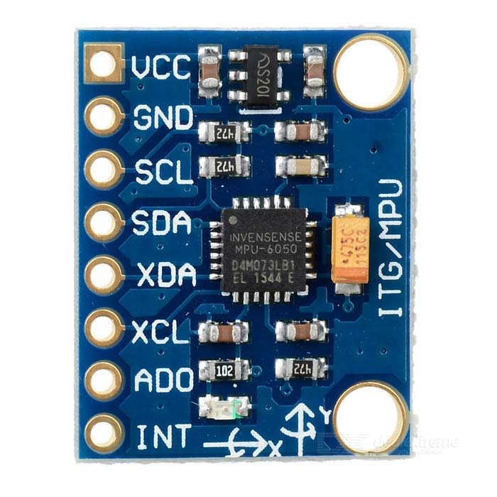
-The MPU-6050 operates with 3.3 volts, although some versions (like mine) have a regulator that allows to connect it to 5V.
-The MPU-6050 uses the I2C communication protocol. In this tutorial I will not go into details of how this protocol works, just make sure to connect the SCD (data) and SCL (clock) pins between the module and the microcontroller.
Part3.1.1 The accelerometer
The accelerometer measures the acceleration. Who was going to say taht?¿. We will have the acceleration of the 3 axes: X, Y and Z, the three dimensions of our 3D space. Let's just call for example, the IMU movemnet upwards, the Z axis, forward and backward the Y axis and side to side the X axis. If you remember feom first grade (or equivalent) classes, you will remember that Earth's gravity has an acceleration of approx. 9.8 m / s², perpendicular to the ground. Therefore, the IMU also detects the acceleration of terrestrial gravity. But the values that we get from the IMU won't be in "g" units. This module works with 8 bits registers. Each acceleration value is stored in two registers, low and high bits. The sum of this registers give us 16 bits of data. This data will have a maximum of 16 bits so we will have a 2^16=65536 maximum acceleration valueincluding the positive or negative sign. If we read the datasheet of this module we will find that "1g" equals to 16384. So if we read the acceleration value and divide that value to 16384 we obtain the acceleration in "g" units.
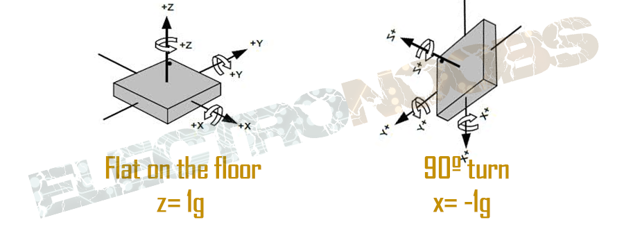
Thanks to terrestrial gravity you can use the accelerometer readings to know the angle of inclination with respect to the X axis or Y axis.
Suppose the IMU is perfectly aligned with the floor. Then, as you can see in the picture below, the Z axis will be 1g=9.8, and the other two axes will be 0. Now suppose we turn the IMU 90 degrees. Now it is the X axis that is perpendicular to the ground, therefore it will mark the acceleration of 1g gravity.
We know that the gravity is 9.8 m / s², and we know how to measure the three axes of the accelerometer, by trigonometry it is possible to calculate the angle of inclination of the IMU. The formulas to calculate the angles are:
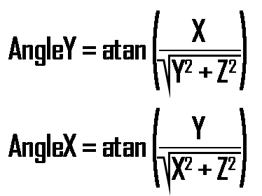
Since the angle is calculated from gravity, it is not possible to calculate the angle Z with this formula or with any other. To do this you need another component: the magnetometer, which is a type of digital compass. The MPU-6050 does not carry a magnetometer, and therefore can never accurately calculate the angle Z. However, for the vast majority of applications only the X and Y axes are needed.
Part3.1.2 The gyroscope
At first, electric gyroscopes were bulky artifacts that were worth most of a state's military budget. Later, during the Second World War they were used to direct rockets and torpedoes. Luckily, thanks to the digital revolution and the miniaturization of circuits, nowadays any fan of electronics can afford one. Although not to build missiles.
The gyroscope measures the angular velocity. If you do not have very fresh your institute physics lessons I will remind you that the angular velocity is the number of degrees that is rotated in a second so our units will be degrees/second.
If we know the initial angle of the IMU, we can add the value that marks the gyroscope to know the new angle at each moment. Suppose we start the IMU at 0 °. If the gives us out a measurement every second, and marks 3 on the X axis, we will have the angle with this simple formula:

Where elapsedTime is the time that elapses each time this formula is calculated inside of the loop, PreviousAngle is the angle calculated the last time this formula was called and GyroData is the reading of the angle Y or X of the gyroscope. And the same thing happens with all the axes. Only the Z axis is usually ignored, since when you can not calculate an Z-angle with the Accelerometer, you can not apply a Supplementary Filter for the Z-axis. We already have the readings. Simple, right? Well, not really.
Part3.1.3 Noise errors and filters
In an ideal world where fairies and elves sing joyous and sweet songs around bonfires, where dragons cross the skies, trees speak with mushrooms and C ++ does not cause errors at runtime, IMUs are magical artifacts that with a little Of trigonometry can give an angle with total accuracy. But you're in the real world, son. And there are two very important problems: noise and errors. Noise is all that interferes with electronic devices. The accelerometer is able to measure any angle, however its readings are noisy and have a certain margin of error. If you ever want to draw a graph of the measurements of an accelerometer as a function of time, you will see something of this style:
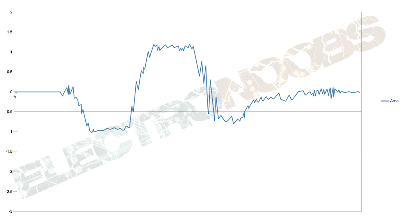
As you can see the raw acceleration data acts like crazy. Even with a low pass filter there would still be peacks and noise. And if we add the angle obtain from the gyro this would be even more crazy. If we obtain the angle using euler formulas and this acceleration data the angle won't be precise in eny moment. For that we should use filters and make a combination between gyro and acceleration data.
The idea is very simple: you have to eliminate the noise, the drift and get the accelerometer to not change its angle when it detects a force other than gravity. There are different algorithms, called filters, that do this task. One of the best is the famous Kálman Filter, which you may have heard of. It is used in aircraft, rockets and geostationary satellites. Kálman's filter is surprising. It is considered one of the greatest finds of the last century, and rightly so. Able to calculate the error of each measurement from the previous measurements, remove it and give the actual value of the angle. In a few words is an algorithm that learns in each iteration. It does not sound too bad, does it?
However it has two problems:
-It has a somewhat high processing cost
-It is very complicated to understand. And I emphasize the "very".
So, we have other filters at our disposal. The one we are going to use is known as Complementary Filter. It is ideal to implement with Arduino: easy to use, low cost of processing and with a very good precision. What exactly is it? The Complementary Filter is actually a union of two different filters: a High-pass Filter for the gyroscope and a Low-pass Filter for the Accelerometer. The first lets only pass the values above a certain limit, unlike the Low-pass filter, which only allows those below. The formula resulting from combining (complementing, hence the name) the two filters is:
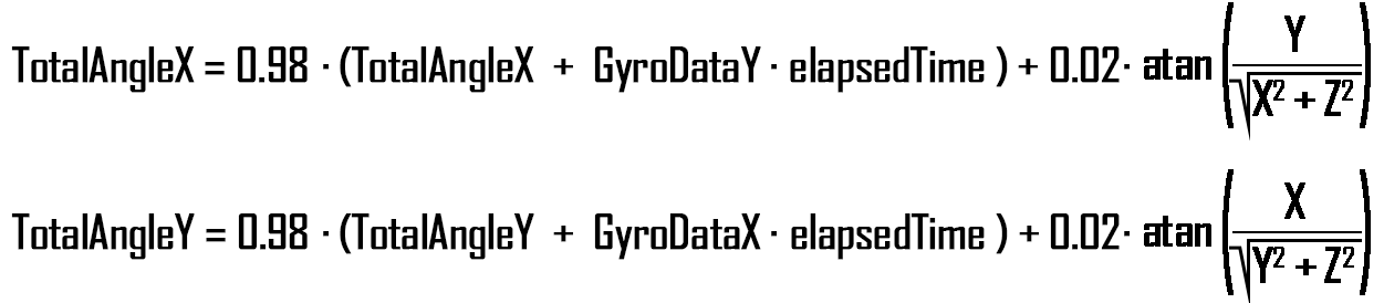
It's not that complicate right? It is just 98% from the angle obtained with the gyro data and a plus of 2% of the angle obtained with the acceleration data. As you can see for the total angle X we sum the gyto data Y. That is because the inclination angle of the X axis is given by the Y axis rotation. Now we have our angles. After applying the filters we should get something like the graph below which is closer to the reality.
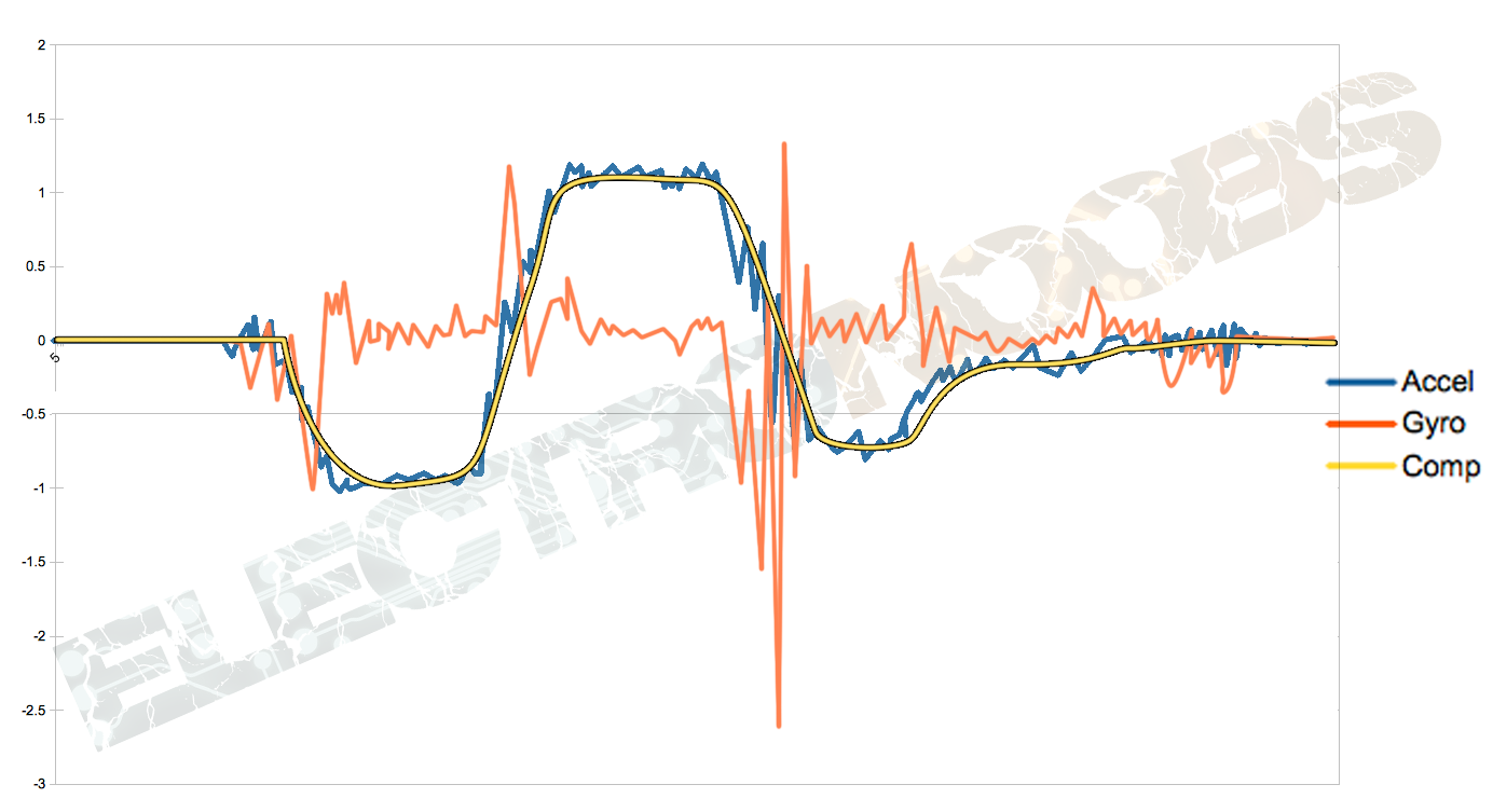
Now we can clearly see the yellow real representation of the angle. This is way better than the raw data. Now all we need to do is to use this formulas in our arduino code to obtain the angle. So let's start with the code.
The connections are very simple. With the USB 5V you will have plenty of power.
MPU Vcc -> Arduino 5v (or 3v3 on some models. Make sure which is yours.)
MPU Gnd -> Arduino Gnd
MPU SCL -> Arduino A5
MPU SDA Arduino A4
Part3.2 The Arduino Code
So let's start explaining the code. In the end we will have the complete code ready to download or copy. IF you want to skip the explination just download the code from the next link:
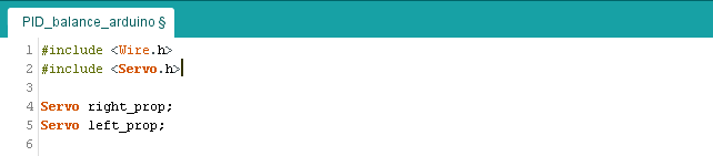
First of all we include the wire and servo libraries. We need the servo.h to create the PWM signal for our ESCs. The wire library will establish a i2c communication with the MPU6050 module. Next we create our servo variables for our two motors, left and right.

MPU-6050 gives you 16 bits data so you have to create some 16int constants to store the data for accelerations and gyro. The data is divided in 2 8bits registers. We will have to sum each pair to obtain the full value.
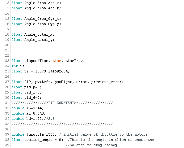
Now we define all the global variables that we're going to use. We ussualy use float variables because we work with real values as well. In the PID constants part is where we will later change the values in order to adapt the program to our system. Each drone will be different so if this code works for me that doesn't mean that it will work with yours. Any way, we will see how to tune the PID constants later. Lets start the setup void.
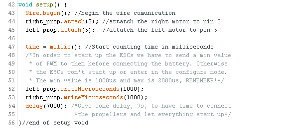
As the code comments say, we begin the i2c comunication and we asign the pins 3 and 5 as our PWM signal outputs. Before all we have to measure the initial time that passed till now. We will use this varible later to calculate the elapsedTime in each loop. The ESCs won't start up if we don't send the min value to them when the LiPo battery or the power supply is connected so for that we send first a 1000us PWM signal to each, because that is the min value that we've deifned when calibrating in this tutorial.
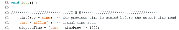
We start the loop and the first thing that we do is calculate the elapsedTime. The elapsedTime is the time that elapsed since the previous loop. This is the value that we will use in the formulas as "elapsedTime" in seconds. We work in ms so we have to divide the value by 1000 to obtain seconds. Now in the next page we can start with the fuul code explained.